AE402

Instructors: Dr. Amnon Katz and Dr. George Weeks

University of Alabama Mini500 Helicopter

CONSTRUCTION LOG

7 Jan 99 AE404 Senior Design class meets for the first time this semester.

Dr. Amnon Katz makes a one hour presentation about helicopter.

Present:

Dr. George Weeks, Students:

Garay, Alan Rufino

Koehler, Christofer Bryan

Mason, Charles Bradley

Watanabe, Misako

12 Jan 99 Large box (B1) and long box (B2) opened and parts inventoried.

14 Jan 99 Shipment of optional parts from Greentree inventoried.

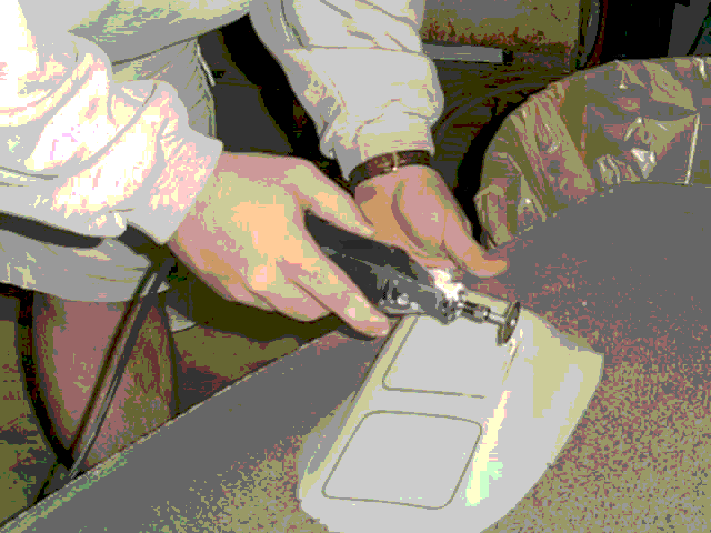
Collecting parts identified in Section 3 (p 1) of Assembly Manual. Starting to trim fiberglass parts to size, using power saw and Dremel tool with cutting wheels. Both blades and cutting wheels wear out. Need additional supply. Safety glasses & hearing btained.

18 Jan 99 Metal blades and cutting wheels now on hand. Trimming following

parts:

BA34 Cabin/Firewall

0667 Console

0674 Turtle deck

0675 Belly scoop

0676 Radiator air shroud


20 Jan 99 Trimming parts above, cutting holes and sanding to shape. Long trim

cuts made with electric jig saw. Short cuts and holes done with Dremel tool and cutting wheels. Holes ground to size with Dremel tool and smoothed with sanding blocks. Winshield T Mounting Brace, #0160 mounted to cabin #BA34. Inlay did not reach core foam. #0160 attached to #BA34 with epoxy and held in place by cleco. A second Dremel tool ordered.

26 Jan 99 Trimmed winshield T (0664). Sanded and fitted turtle-deck (0674) and

belly scoop (0675) to cabin (BA34) and attached with clecos. Sanded and fitted right and left access doors (0671,0673) to parts above and attached with clecos. Inspection doors (0670) and (0672) trimmed and sanded. Windshield T (0664) trimmed. Received external paint, torque wrenches, second Dremel kit. 28 Jan 99 Inspection doors (0670) and (0672) fitted to access doors (0671) and (0673) and held with clecos. Holes in hinges (0537) drilled in place. With hinges clecoed, doors were tested for movement. Hinges marked and returned to VP16. Trimmed bottom of console 0667 to accept indentaion in headlight mount. Trimmed seat (0668) and instrument box (0669). Trimmed tail winglets (0681,0682). Sanded vertical stabilizer (0662) and horizontal stabilizer (0663). Filled void in 0662 with glass impregnated cloth.

02 Feb 99 Sealed foam edges on cabin BA34 and access doors (0671,0673) with 5

minute epoxy and sanded. Sanded uncut edges on bottom of console 0667. Sanded away glass edges on windshield T 0664. Sanded glass filling on vertical stabilizer 0662 and horizontal stabilizer (663). Laid a 3" cloth strip with epoxy on leading edges, then a 2" cloth strip on top of that. Lsft to dry before sanding. Called Greentree, Revolution, Pratt for mixing directions for 483-675 epoxy primer, 702-901 thinner, 120-900 converter. This is required for internal fiberglass surfaces, but ratio not specified in instructions.

04 Feb 99 Cut off flange of intrument box (0669). Sanded all exterior

fiberglass surfaces with 200 sandpaper and all interior surfaces with 120 sandpaper. Removed red inspection tabs from surfaces.

09 Feb 99 Tried to mix No. 17 white filler and found that it has hardened.

Date of manufacture is 6/98 and shelf life 6 months. Ordering replacement. Mixed 487-600 tan fill primer with 120-900 converter and 702-901 reducer (1:1:1 by volume) and treated outside and inside surfaces that need to be painted. Horizontal and vertical stabilizer, turtle deck, and cabin not done today. Cutting door frames to shape with Dremel cutting wheels. Talked to DAR John Burgen (205-836-8390). He has not done a Mini500 before, but it is within his authority. He does not need to see the project ahead of time. Needs 2-3 weeks notice.

11 Feb 99 Replacement filler received. Parts with faults filled: tail

surfaces, conbsole, turtle deck.

12 Feb 99 J. Reeves of FAA Inspection District Office in Atlanta faxes his

answer to our request that he address the class. His schedule does not permit it. Suggests C. Avery and D. South of EAA Chapter 557 (Tuscaloosa) and B. Hensley of FAA in Birmingham.

16 Feb 99 Sanding parts to which filler was applied. Windshield trim parts cut

with electric saw from sheet aluminum (0311) using the (0312) pattern.

18 Feb 99 Sanding filled parts with electric sanders provided by G. Weeks.

More filler applied to rear of console and to turtledeck. 3/16" holes drilled in winshield trim parts as indicated on patterns. Parts were smoothed on chain sander and marked on back in anticipation of removing patterns glued to front. Started cutting honeycomb screen parts from screen (031?) using patterns (031?). Cutting done with Dremel wheel. 23 Feb 99 Finished cutting screen parts. All aluminum parts that need preparation for painting were located and collected (Tail boom, winshield trim pieces, screen parts, landing light retainer, four mounting plates).

Fiberglass parts covered with 1:1 mixture of 482-300 blue epoxy fill primer and 120-900 epoxy converter (blue color) applied with a brush. All parts started, but inside of some not finished because we ran out of 120-900. Ordering: 4 brushes, 2 quarts of 120-900, 1 gal laqueur thinner, 1 gal acetone.

25 Feb 99 Supplies received. 120-900 available only in 1 gal cans. Have 1 gal.

Completed coating of all fiberglass parts. Imprfections in cabin, turtle deck and console filled with white epoxy filler. Started wet sanding. Ordering sprayer to prime Al parts.

02 Mar 99 Finished wet sanding of all fiberglass surfaces to be painted:

outside surfaces, and exposed surfaces in cabin and in engine compartment. Outside surfaces repainted with a 1:1:1/2 mixture of 482-300 epoxy blue primer, 120-900 converter and 702-901 reducer.

04 Mar 99 Wet sanded all outside fiberglass surfaces again with 400 sandpaper.

Widshield T, console, instrument box, seat and radiator shroud painted grey with commercial enamel spray can. Ran out of paint. Metal parts: tail boom, windsheild strips, ldg gear fairings and 6 screen parts washed with MEK (Methyl Ethyl Ketone) and sprayed with (1:1) mixture of 484-684 wash primer and 120-789 converter. The 6 screen parts were then painted black with spray can from prime kit. Dr. Weeks decided to let Ken Dunn's shop do the next step: spraying with (1:1) mixture of 483-675 green corrosion preventer primer and 120-675 converter, thinned with 702-901 reducer, since results from our sprray tool, crown spray gun driven by an aerosol can is not uniform.

05 Mar 99 I deliver to Ken Dunn's shop:

  • 1. the 483-675 green corrosion preventer primer, 120-675 converter, and 702-901 reducer together with the mixing and application instructions.
  • 2. The white outside paint.
  • 3. All aluminum parts that need outside paint:
  • a. tail boom,
  • b. 4 landing gear leg fairings,
  • c. 10 windshield trim strips,
  • d. 4 tail attach plates,
  • e. landing light frame.
  • 4. Fiberglass parts:
  • a. vertical fin,

  • b. horizontal stabilizer,
  • c. 2 end plates,
  • d. landing light holder.
  • The fiberglass parts that make the engine compartment were retained and painted on the inside with yellowish epoxy paint. These parts were:

  • a. cabin,
  • b. turtle deck,
  • c. belly scoop,
  • d. 2 access doors,
  • e. 2 inspection doors.
  • All parts, except turtle deck, given 2 coats today.

    06 Mar 99 Second coat applied to inside of turtle deck.

    08 Mar 99 The parts delivered have been painted (3 coats) and are curing. The>

    College shop almost ran out of paint (1 gal can) and ran out of a flexing additive. After some searching, Tim Connell (AEM department technician) found the required supplies locally:

  • Automotive white paint 2 gals
  • (PPG DCC Linen White Paint GM#2285)
  • * Flexing agent 1 quart
  • * Reducer 1 gal
  • These supplies were delivered to the COE shop.

    09 Mar 99 The parts painted (lists 1 through 4, above) brought back to room

    119. The remainder of the parts needing outside paint, namely:

  • a. cabin,
  • b. turtle deck,
  • c. belly scoop,
  • d. 2 access doors,
  • e. 2 inspection doors.
  • delivered to COE paint shop.

    Heat shroud cut according to pattern. Started fitting snap fasteners to part that needs them. Installation tool failed.

    11 Mar 99 Belly scoop connected to cabin with screws into anchor nuts

    installed in lip of cabin. Inspection doors installed on access doors. Turtle deck connected to cabin and belly scoop with clicos. Started drilling 1/2 inch holes on these parts to accept camlocks for access door. Decided to use screws instead of epoxy to attach screens.

    16 Mar 99 Installing camlocks in access doors. Left door complete.

    17 Mar 99 Finished camlock installation. Screens held in place with screws and

    washers: washers on outside, nuts on inside screen side. Then edges of screens secured in place with epoxy. Epoxy ran to outside, will require removal of beads on outside.

    18 Mar 99 Cannot find right door heat shield. Will have to order more heat

    shield material. Installed heat shields on belly scoop and exhast opening of turtle deck. Heat shield attached in place with contact cement. Found that contact cement dissolves the epoxy paint used on inside of engine compartment. This paint stripped of areas supporting the heat shield and the heat shield was attached to blue primer. Other heat shield pieces saved in paper bag. 21 Mar 99 Completed installing snaps in "cable heat shield" at home using a better tool (plier).

    25 Mar 99 Rubber trim attached to turtle deck openings (3 places), edges of

    landing gear leg fairings (8 places) and landing light mount (1 place). Contact cement from Revolution kit fails to adhere to rubber. Strips of trim held in place with clips and left to cure. Also attached piece of heat shield to left side of turtle deck.

    13 Apr 99 Finishing clean up of engine compartment parts.

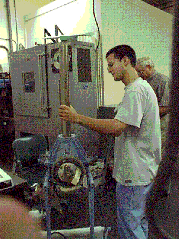
    Starting to assemble cooling fan. Using oven calibrated to 190C and deep freeze measured at -20C. Heated bearing 0568 for 15 min and mated with cooled part 240. First attempt failed. On second attempt, a press was used to mate parts successfully. Mating of heated 0029 hub with frozen 0568 bearing was much easier. Press was used, but parts seemed to almost fall into place. Loctite applied before assembly.

    Temporarily assembled fan with bolt holes aligned, but alignment not good enough for bolts to go through.

    14 Apr 99 Pressed temporarily assembled part and this causes holes to align.

    Marked alignment on 0228 and 0229 and disassembled, marking location of each blade. Completed the cooling fan assembly per instructions. Installation of 0568/0240 into 0228 was easy. Fitting 0229 was difficult and required considerable presure on press.

    16 Apr 99 New heat shield kit received. Right access door shield cut per

    pattern.

    20 Apr 99 Heat shield attached to right access door with contact cement. Epoxy

    paint was stripped from contact area to blue primer by sanding. Fan belt idler for cooling fan assembled in two heating/cooling steps per instructions (p. 5-8). Transmission removed from temporary storage on frame. Cooling fan and idler assembled to frame. 0244 sleeves did not fit into sleeves on BA01 frame. Required sanding of inside of frame sleeves and some tapping. Lock nuts not tightened. 22 Apr 99 Drive belt idler wheel assembled in two heat/cool steps per instructions (p. 5-8). The whole drive belt idler assembly put together and attached to BA01 frame. Lock nuts not tightened. Tail rotor drive shaft assembled. Two 0035 bearing bushings slid into place heated and secured with roll pins 492. JB Weld not applied yet. Splined coupler 0069 attached to one end with 0070 spacer and two bolts. Companion flange BA19 attached to other end with two bolts.

    27 Apr 99 Put beads of JBWeld on inside ends of bearing bushings 0035 where

    they meet tail rotor drive shaft as shown in Fig 19, p. 5-9. Assembled throttle corelator per instructions (p 5-17). Junction box spring cap 0199 required reaming before it could be mounted on junction box shaft 0202. Lock washer 0453 included in parts list is not mentioned in drawings and instructions. Returned to VP18.

    04 May 99 Assembled tail boom per instructions on pp. 5-9,10 through

    instruction 19. 2 drive shaft bearing retainers (0036) were frozen prior to insertion in boom to permit sliding them through. This was done with a tool consisting of a round plate with two bolts at the end of a long metal pipe. This tool was used both for insertion and turning. Aft retainer was pushed too far and returned to place by tapping from aft side. Step 18 was accomplished by first threding a string through the two holes in the boom and around the combination of control cable and harness. The string was then used to pull the tie around. Attempted step 20, but found it too hard to slip fire sleeve 0343 on on control cable 0428. Attempted step 21, but found that bearing 0572 on drive shaft could not pass through opening in retainer 0036.

    ===============================================================================

    25 Aug 99 AE402 Senior Design class meets for the first time for Fall 1999.

    Instructors: Dr. Amnon Katz and Dr. George Weeks

    Gomeringer, Timothy Mi

    Hutson, Stephen Andrew

    Jones, Jennifer Elaine

    Kornegay, Clayton Ward

    Lenski, Raymond Roger

    Othman, Muhammad Firda

    Shackelford, Carla Vic


    First 3 weeks devoted to preliminary design exercise.

    Team 1: Gomeringer*, Hutson, Jones.

    Team 2: Lenski*, Kornegay, Othman, Shackleford

    * Team leader.


    CONTINUED CONSTRUCTION


    20 Sep 99 TEAM 1 measured 0030 mast and 0009 tie mount, Results:

    Mast OD at tip 2.2470 - 2.2515 in

    Tie mount ID 2.2495 - 2.2505 in

    Team sketched support bearing mount and selected bearing

    TEAM 2 report (R Lenski)

    [The team finished the Tail Boom Subassembly:]

    1. slipped fire sleeve #0343 over forward end of cable.

    2. inserted assembled drive shaft into boom tube.

    [The team started work on the Tail Rotor & Controls

    Subassebly.]

    3. Tail Rotor & Controls:

  • a. separated the required items for assembly
  • b. read carefully through the instructions
  • c. obtained a thermocouple for heating control
  • d. turned on the freezer.
  • e. unsuccessfully attempted assembly of the tail rotor and determined the need for freezing.
  • f. [4 bearings 0602 and bushing 0053 placed in freezer.]
  • TEAM 3 report (J Jones)

    [The team started work on the Console Frame & Cyclic Control Subassembly.] ... collected and labeled all the parts for the We have started on the stick, but the cyclic vibration damper 0279 needs to be grooved out further before the stick can be complete. We've also started on the console frame.

    21 Sep 99 Cyclic vibration damper 0279 regrooved by T. Connell to make room

    for cable of custom stick grip.

    22 Sep 99 TEAM 1 Made drawing of MS fitting & selected

  • bearing SKF #6214-2RS1 (2 seal) (p. 198) and
  • outer spiral lock ring #WSM-275 (p. 28)
  • Making templates to fit blades to measure twist. Determined that blades can be weighed in AE Structures lab.

    TEAM 2 [The team continued work on the Tail Rotor & Controls

    Subassebly and started on Fuel & Oil Tank subassembly.]

  • Freeze bushing 53, heat bearing 569 and connect the two. 2. Freeze 53 & 569 combined, heat tail rotor control housing 52 and combine with 53 & 569. 3. Assemble tail rotor blades, tail rotor hub plates 56, and tail rotor hub block 57.
  • Section 5 pg 21 Oil and Fuel Tank Completed entire oil and fuel tank assembly. The only step left is to clean the oil and fuel tank using gasoline.
  • TEAM 3 Reworked damper 0279 and cyclic handle tube 0147 to fit

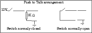
    custom grip. Roll pins removed & screws used instead after drilling & tapping holes in 0147 and elbow 0100. Grip assembled to tube. Started checking functionality of swithches. Push-to-talk switch grounded when released.

    23 Sep 99 A. Katz finalizes MS fitting with material (4130 Steel, annealed)

    and dimension tolerances. Bearings and spiral lock rings ordered.

    24 Sep 99 MS fitting drawing submitted to COE machine shop (Mr. Ken Dunn).

    27 Sep 99

    Team 1 [Othman] Weight of blades determined:
  • Blade A: 18.99 lbs
  • Blade B: 18.98 lbs
  • Team 2 [Lenski]
  • 1. Section 5, pg 21: riveted the gas tank filler neck.
  • 2. Section 5, pg 11:
  • a.Installed rod end #0600 onto tail rotor control housing #0052.
  • b.Slipped tail rotor control housing #0052 assembly over tail rotor shaft.
  • c.Lubricated notches in tail rotor control yoke #0054 with white lithium grease and installed ball bearings.
  • d.Bolted tail rotor control yoke #0054 to tail rotor control bushing #0053.
  • e.Attached rod end #0600 to bellcrank arm #0115
  • NOTE: Bolts not torqued pending suitable torque wrench.

    Team 3 [Hutson] The wiring for the cyclic stick was tested and functions as follows:
  • green button -- toggle on/off
  • black button -- toggle on/off
  • blue button -- toggle on/off
  • red button -- hold to engage
  • trigger -- hold to engage
  • "wabble hat" -- hold up/down/side/side to engage
  • The console frame and cyclic control is partially assembled. The two will be connected next class. The friction lock and Anti-torque push rod are in place. The cyclic front mounting block 0152 would not fit in main control rod 0167. Sanding away paint did not help. Put 0152 in the freezer.

    29 Sep 99

    Team 1 [Othman] The twist angles for both of the main blades was determined, and found to be 6.5 degrees. We found approximately the location of the Mast Support bearing on the mast, which is 11.5 inches from the top of the shaft. The location was marked.

    We also found a place to hang the blades for the pendulum experiment to determine the moment of inertia. It is in the Aerospace Structures lab.
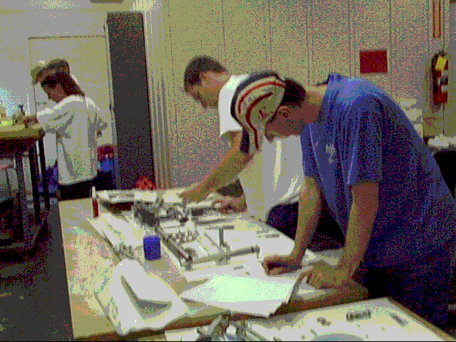
    Team 2 [Lenski]
  • 1. Tail rotor subassembly: Section 5, pg 11: Secured bolts #0360 with safety wire.
  • 2. Collective and throttle subassembly: Section 5, pg 19: finished collecting pieces for the sub-assembly and put together entire structure. Torquing needed on all bolts
  • 3. Oil and fuel tank subassembly: Section 5, pg 21: cleaned gas tank and oil tank with gasoline. This subassembly now complete.
  • Team 3 [Hutson]

    Frozen front mounting block 0152 mated with control main tube 0167. Cyclic fork 151 did not fit over cyclic stick BA13 until heated. The the cyclic control subassembly is complete except for torquing the nuts.

    Started on console assembly.
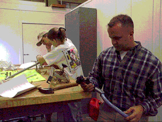
    
    
    04 Oct 1999  Team 1 [Othman]
                 Designed the pendulum experiment to determine the moment of
                 inertia of the blade. Selected location in Structures lab. A
                 threaded bar is to be secured with nuts and washers to a hole in
                 the support structure in a horizontal orientation and serve as 
                 hinge for the pendulum. The blade is to be mounted on the bar 
                 through one of the bolt holes. The only available bar did not fit
                 the holes of the blades. We made a sketch of the intended bar.
    
                 Team 2 [Lenski]
                 Subassembly:  Tail & Rotor Control (Section 5, pg 11-12)
                 The bolts for the entire subassembly were torqued down with
                 the new torque gage wrench.  The assembled tail rotor (#0056, 
                 #0057) was attached to the tail rotor center mount (#0058) per 
                 fig. 23.  The pitch links (#0592, #0593) were assembled.  The 
                 washers #0473 had to be sanded to fit.  The bolt #0364 with 
                 washer & spacer was attached to the tail rotor hub #0057. This 
                 completed the subassembly.  Parts called for but not used:
    
                   #0473 washer  quty 8,
                   #0597 rod end      1,
                   #0472 washer       5, 
                   #0455 nut          1,
                   #0362 bolt         1.
    
                 Subassembly:  Collective & Throttle (Section 5, pg 19-20)
                 The bolts for the entire subassembly were torqued down with
                 the new torque gage wrench.  This completed the subassembly.
                 Parts called for but not used:
                   #0456 nut     quty 2,
                   #0370 bolt         2, 
                   #0361 bolt         1.
    
                 Team 3 [Shackelford]
                 The console frame and cyclic control subassembly: 21 bolts 
                 tightened with a torque wrench. Subassembly is finished. There 
                 were a few parts called out for the subassembly, but not used, 
                 namely:  
    
                 quantity   part no.  name of part        (comment)
                 ----------------------------------------------------------
                    2 -     #0068   Multifunction 5/16 Spacer
                    4 -     #0483   Nylon Washer 1/4 (also called for final
                                                               installation) 
                    4 -     #0491   Spring Pin 1/8x1 (replaced by screws)
                    1 -     #0521   End Plug 1" ( superseded by custom grip)
    
    
                Started pulling the parts out for final assembly for the console 
                frame installation.  
    
    05 Oct 1999 Sketch of bar for pendulum experiment delivered to COE machine
                shop with work order.
    
    
    06 Oct 1999 Team 1 [Othman]
                The main rotor blades were hung from the inboard bushing and
                swung.
                Their natural frequency of oscillation was determined. Each blade
                was timed for 25 cycles, and this was repeated three times.
                The results were
    
                 Blade                   A                     B
                 25 perids (s)   69.19, 69.06  69.03   69.04, 69.10, 69.24
    
                 From this, the period was determined as
    
                 Period (s)         2.764 +- 0.003       2.765 +- 0.003
    
                The CG location of the blades was found by supporting the blade at
                the inboard bushing and a point 100 inches outboard of this point
                and recording the weight supported at the busing. The raw results
                were
    
                Weight @ bushing (lb)     9.27              9.28
    
                The blade weights had been determined on 27 Sept
     
                Weight of blade (lb)     18.99             18.98
    
                From this, the CG location relative to bushing is determined as
    
                CG location (in)         51.18             51.11
                from bushing
    
                From these data the mass moment of inertia of the blades about the
                inboard bushing was computed:
    
                J' (slug x ft^2)         15.67             15.66
    
    
                The entire transmission & mast unit was cooled in the freezer and
                the mast support fitting was heated to 450 F. The the two were
                mated. The fitting was loose on the mast. The measurements of the
                mast and fitting #0009 taken on 20 Sep had shown both these items
                out of round. The fitting had been sized for the larger dimension.
                It was now found that lower down, the mast was round and the
                fitting proved too large. After temperatures equalized, the
                fitting was removed from the mast by hand.
    
     
                Started collection of parts for the rotor head & conrols 
                subassembly.
    
                Team 2 [Lenski]
                Subassembly: Tail & Rotor Control (Section 5, pg 11-12)
                The unused parts were bagged and returned to the original
                boards.  Parts:
    
                 VP4 #0473 washer quty 8,
                 VP7 #0597 rod end 1,
                 VP4 #0472 washer 5,
                 VP4 #0455 nut 1,
                 VP1 #0362 bolt 1.
    
                 Subassembly: Collective & Throttle (Section 5, pg 19-20)
                 The unused parts were bagged and returned to the original
                 boards.  Parts:
    
                 VP4 #0456 nut quty 2,
                 VP1 #0370 bolt 2,
                 VP1 #0361 bolt 1.
    
                 Cleaning House
                 Several parts were repacked in bags that were poorly
                 attached to the boards. Parts:
    
                  board: VP1 #0357 bolt
                    #0361 bolt
                    #0364 bolt
                    #0369 bolt
                    #0370 bolt
    
                  board: VP4 #0450 washer
                    #0455 nut
                    #0456 nut
                    #0475 washer
                    #0478 washer
    
                  board: VP7 #0597 spherical rod end
    
                 Subassembly: Cooling Fan (Section 5, pg 6)
                 The bolts for the entire subassembly were torqued down with the new torque
                 gage wrench.  This completed the subassembly.
                 Deviations:
                   Two washers were placed incorrectly and fixed.
    
                 Final Installations: Radiator & Shroud (Section 6, pg1)
                 Installations went per instructions with two deviations:
    
                 1. The RTV to seal the screw was not available, instead used 
                    (#0513) methacrylate adhesive.
                 2. Two of the washers (#0477) did not fit on the shroud (#0676)
                    and radiator (#0636) connection as described in step#5.  The 
                    washer was cut as illustrated.
    
    
                Team 3 [Shackelford]
                Final nstallation: Console frame installation
    
                Seven 1/4-inch holes were drilled into the console & #0554 
                screws inserted in them to attach the console frame assembly to 
                the console. The push rods had to be turned forward on the 
                assembly. Then the pedal tubes #0161 and #0162 were inserted 
                through the console. The anti-torque bell horns #0143 were 
                attached to the pedal tubes with #0369 bolts called out on the 
                parts list. The #0368 bolts indicated in Figure 11 were too short.
                The anti-torque push rods #0178 were attached to the second hole 
                of bell horns for medium sensitivity. #0370 bolts called out in 
                the parts list were used with two extra washers. The #0368 bolts 
                shown in Figure 11 were too short. At this point, it was realized
                that the cyclic stick had not been attached to the console frame.
                It appeared that it should be attached. To achieve this, the 
                console frame subassembly had to be detached from the console (the
                lock nuts had not been tightened yet). With the cyclic stick in 
                place, the assembly was reattached. The cyclic stick was then 
                connected to the console frame assembly per Figure 27 of Section 
                5. The seven screws that attach the console frame to the console 
                were torqued until the composite on the outside started to crush.
                Many bolts on this assembly are not torqued yet.
    
    11 Oct 1999 Team 1 [Othman]
                Subassembly: Rotor Head & Controls
                Pressed 4 bushings (0562) into 2 control rods (BA16).
    
                Finished collecting all the parts for the subassembly.
    
                Mast Support
                The fitting was cooled for about one hour in the freezer while the
                bearing was heated to 350F. 
                The bearing, painted with Locktite, was easily placed on the
                fitting and became fixed in place after cooling. The retainer ring
                was installed. The completed part was then placed on the mast and
                secured with JB Weld leaving 11.5 in. from the top of the shaft to
                the top of the fitting.
    
                Team 2 [Lenski]
                Final Installations: Airframe on Legs (Section 6, pg2)
                1. The parts were collected for the assembly.
                2. The positive and negative battery cables (#0532, #0533) were 
                cut and stripped to the lengths specified in the manual.
                3. The battery cable ends (#0529, #0531) were crimped to the 
                battery cables (#0532, #0533) and soldered using a propane torch.
                4. The heat shrink (#0534) was heated onto the exposed battery 
                cables (#0532, #0533). (On the 12” positive cable (#0532) the 
                solder melted through the heat shrink. This was repaired with 
                electric tape.)
                5. The ground wheel skid bracket (#BA07) was attached to each 
                skid (#BA02) with steel rivets (#0488). (One rivet did not seat
                properly and was removed. A replacement rivet is needed.)
                6. The right rear landing gear strut (#BA05) and right front 
                landing gear strut (#BA03) was attached to the landing gear skid 
                (#BA02). NOTE: It was difficult to align bolt holes.
    
                Team 3 [Jones]
                Console frame installation final assembly:
                * Torqued nuts (4) connecting pedal tubes to push rods.
                * Torqued nuts (2) connecting cyclic stick to friction lock
                The Console frame installation final assembly is complete per
                manual.
    
                *Parts remaining:
    
                  Quantity    Part            Part #
                --------------------------------------
                   (1)  Left pedal             0141
                   (1)  Right pedal            0264
                   (4)  Screws 1/4x28 1 5/32   0367
                   (2)  Pedal tube plug        0265
    
                 Mounted Optional Radio Rack in Console:
    
                Drilled mounting holes in console per instructions. Edges of radio
                rack had to be ground for proper fit. The bottom right hole in 
                console frame had to be enlarged for proper alignment of bolts. 
                Used bolts and washers provided with radio rack, however, two 
                extra 3/16 washers are needed on each of 6 bolts that connect 
                radio rack to console frame - short 12 washers. Lock nuts not 
                tightened pending washer availability.
    
                Collected parts for Console to Cabin final installation.
    
    13 Oct 1999 Team 1 [Othman]
                Mast support
               
                Design of stationary fitting discussed and agreed.
                Measured the outer diameter of the mast support bearing. Values
                obtained at different azimuths are:
    
                   4.9208 in.    4.9205 in.
                   4.9206 in.    4.9205 in.
                   4.9210 in.    4.9205 in.
                   4.9208 in.    4.9205 in.
    
                Subassembly: Rotor Head and Controls
                4 bushings(#0562) were pressed into lower mount block(#0029).
                4 bushings(#0562) were pressed into upper mount block(#0038).
                2 bushings(#0562) were pressed into teeter block yoke(#0027).
                2 bushings(#0562) were pressed into control yoke(#0024).
                Upper mount block(#0038) and teeter block yoke were mounted by 
                  2 shoulder bolts(#0441). Threads were secured with #262 red 
                  locktite.
                Lower mount block(#0029) and teeter block yoke were mounted by 
                   2 shoulder bolts(#0442) and 2 washers(#0475) and 2 springs 
                   (#0497). However, parts were misinstalled with the wrong end of 
                   #0029 facing #0027. Therefore, parts were dissembled after 
                   heating. Will be reassembled next time.
    
                Team 2 [Lenski]
                Final Installations: Airframe on Legs (Section 6, pg2)
                The installation was completed and the following parts were 
                unused:
                        #0533 (24” and 12” negative cable with attachments)
                        #0532 (57” and 12” positive cable with attachments)
    
                Final Installations: Collective to Airframe (Section 6, pg3)
                The installation was finished as instructions specified with the
                following Deviation: Washer (#0479 SS flat washer 1 /4 X 5 /8 X 1/16) 
                was missing. Instead, 2 (#0473 1 /4 X 1 /2 X 1 /16) washers were 
                used with the bolts that attach the collective torque bar (#BA15)
                to the airframe.
    
                Final Installations: Engine (Section 6, pg14-16)
                Collected parts for installation.
    
                Teeam 3 [Jones]
    
                Console, installation of optional Radio Rack:
                Added 3 extra 3/16 washers (not included in optional radio rack 
                kit) to to each of the 6 bolts that connect the radio rack to the
                console frame - new washers were  thinner than original washers
                Torqued 6 bolts connecting radio rack to console until the console
                was slightly indented
    
                Optional Radio Rack is installed - all parts used.
    
                Console To Cabin final installation:
                Drilled 6 (1/4") holes into console frame and attached (2) seat 
                brackets #0164 per instructions (pp. 6-6).
    
                Bonded 3 layers of aluminum foil (Reynolds wrap) approximately 
                0.015" thick to floor of cabin using 5 min. epoxy - needed 
                as ground plane for navcom & transponder antennas.
    
    18 Oct 1999 Team 1 [Othman]
                Subassembly:Rotor Head & Controls
                1. Remounted teeter block upper yoke mount #0038 & teeter block yoke #0027 
                   using 2 #0441 shoulder bolts.
                2. Froze hub #0025 for two hours.
                3. Heated bearing #0577 to 350F for 15 minutes.
                4. Applied a thin film of Loctite #7331 to hub #0025; assembled 
                   hub #0025 and bearing #0577.
                5. Installed spiral lock #0612 to hub #0025
                6. Frozshace bearing #0577 and hub #0025 assembly for one hour.
                7. Heated control transfer plate #0023 to 350F.
                8. Assembled the bearing #0577 and hub #0025 assembly into the control 
                   transfer plate #0023; a thin film of Loctite #7331 stud mount 
                   was applied to the control transfer plate #0023 before assembly 
                   but burned off due to excessive heat.
                9. Spiral lock #0616 was installed into control transfer plate #0023
               10. #0024 yoke was attached to hub #0025 using three #0433 cap 
                   screws; #242 blue Loctite was applied to the screws before 
                   assembly.
               11. Control yoke teeter block #0026 was attached to control yoke 
                   #0024 using 2 bolts #0365, 2 flat washers #0479, 4 teflon washers 
                   #0101, and 2 1/2 inch sleeves #0017; #0101 teflon washers needed 
                   to be sanded to allow teeter block #0026 to move freely; #242 
                   blue Loctite was applied to 2 bolts #0365 before assembly.
               12. 2 #0017 sleeve were trial fit into #0026 control yoke teeter
                   block; ends of #0017 sleeves were sanded to allow for slip fit.
               13. 2 #BA16 control rod assemblies were installed into control yoke 
                   teeter block #0026 using 2 bolts #0434, 2 nuts #0470, 2 1/2"
                   sleeves #0017, 4 teflon washers #0101.  Heads of bolts #0434 
                   were opposed and are in the direction of rotation; bolts holes 
                   in #0026 control teeter block were chamfered with a 5/8 inch 
                   drill bit so that head of bolt #0434 would seat flush.
    
                Team 2 [Lenski]
                Final Installations: Engine (Section 6, pg14-16) 
                1. Enlarged hole in washer (#0480) and removed 4 existing studs 
                from bottom of crankcase.
                2. Installed 8 isolator mounts (#0500) into the inner two holes 
                of engine mounts (#0113) as shown in figure 35.
                3. Installed electric starter as specified.
                4. Repositioned oil reservoir as specified.
                5. Installed thermostat as specified.
                6. Replaced brass nipple with bolt (#0443). Instructions called 
                   for it to be sealed with RTV Loctite #72B (doesn't exist) 
                   used Loctite #26B instead.
                7. Installed temperature probe as specified.
                8. Moved ground wire and wrapped with other wires.  Replaced wire connectors.
    
                Team 3 [Hutson]
                Console to cabin installation. Decided to mount optional xponder &
                   VHF antennas to bottom of cabin before attaching console to 
                   avoid later problems with access to wiring.
                   Installation of Pitot/static probe also advanced to this stage.
    
                Re-drilled console to cabin floor holes in belly of cabin.
    
                Pitot Tube: Peeled back aluminum foil at the bow of the cabin to 
                locate pre-drilled holes for pitot tube installation in the
                bottom of the cabin (Holes did not show on outside. Possibly they
                were covered during painting.) Holes drilled to fit pitot tube.
                Tube Mounted with the following hardware:
                       Bolt   #358 (2)
                       Washer #472 (2)
                       Lock Nut #455 (2)
                Nuts tightened to fit without torque wrench because bolts carry no 
                load.
    
                Transponder antenna: Placed on cabin bottom centerline behind
                Pitot. Drilled 2 holes using 3/16 drill bit and one 9/16 inch hole
                for connector per antenna mounting template. Put antenna in place
                to test clean cable hook-up. Used back-plate and 3/16 lock nuts 
                (2), and lock washers (2) supplied with antenna.
    
                VHF antenna:  Placed behind the Xponder antenna, directly between
                third set, from the bow, of console mounting holes on cabin bottom
                to keep whip antenna under ground plane. Drilled 4 holes in
                bottom. Mounted with 4  5/16 flush-head screws to mount & square
                nuts. Drilled 9/16 inch hole for connector.
    
    20 Oct 99   Team 1 [Othman]
                Subassembly: Rotor Head & Controls
    
                1. 2 nuts (#0470) were torqued for the control rod (#BA16) and 
                   control yoke teeter block assembly.
                2. Control rods were ??? and the lower control assembly at the 
                   bottom of the mast were done. Bolts (#0387) were installed with 
                   safety wire.
                3. Upper control blocks (#0016) were assembled to teeter block 
                   yoke(#0027) by 4 teflon washers (#0101), 2 bushings(#0562), 2 
                   half inch sleeve (#0017), 2 flat washers (#0479), 1 bolt (#0376
                   and 1 nylock nut (#0456).
                4. Rubber sleeve (#0272) was installed on mast.
                5. Tie block (#0009) was heated to 400F for 1 hour. At the same 
                   time, the transmission & mast were cooled in freezer.
                6. Tie block(#0009) then was installed on the mast and holes 
                   aligned with a 3/8 drill bit.
                7. 2 spherical bearings (#0603) were cooled in the freezer for 
                   1 hour. One bearing was pressed into hub plate (#0012), which
                   was heated to 350F. When the process was repeated with second
                   bearing & hub plate, the bearing went in tilted and had to be
                   pressed out (2 tries).
    
    
                Team 2 [Lenski]
                Final Installations: Engine (Section 6, pg14-16)
                Installation finished with these exceptions pending:
    
                1. Did not install spark plugs (no antiseize)(step#8).
                2. Did not adjust main drive belt (transmission not on airframe) 
                   (step#18).
                3. Did not tighten bolt (#0436) to clutch (lack of tools) (step#19).
                4. Did not attach and adjust tension bars (#0133) to transmission 
                   (transmission not on airframe)(step#21).
    
                One deviation: The engine did not lock using the supplied tool.  
                Instead, held gears near starter (step#12).
    
                Team 3 [Hutson]
                Continued installation of optional antennas related wiring.
    
                VHF antenna: Shortened cable and installed "Solderless BNC for 
                RG-58 Coax" connector from Radio Shack. test for connectivity 
                successful. Hole in cabin bottom had to be enlarged to make room 
                for connector. Removed antenna to rework hole. Remounted antenna 
                with new bolts (5/16 flush-head screws, as before) and correct
                nuts.  Nuts used previously did not match screw thread and wore
                out thread.
    
                Headset jacks (2) mounted to right side of console, separated by 
                2.5 in. Desired location (below seat) was not obtainable due to 
                short length of wires.
    
                GPS antenna:  To be mounted on uppermost flat surface on outside 
                of cabin. Drilled hole in rear right corner of console and passed
                GPS antenna cable through. cable will be placed under interior 
                carpeting, running along inside right rear corner of cabin.  
    
                Altitude encoder: Mounted to radio rack in predesignated location.
                Encoder plugged in and tightened.
    
    25 Oct 99   Team 1 [Othman] Subassembly: Rotor Head & Controls
    
                1. Yoke stabilizer block (#0137) was bolted to Yoke stabilizer arm
                (#0138) using bolt (#0382), 4 teflon washers (#0101), 2 flat 
                washers (#0479), 2 flat washers (#0473), 2 1/2 inch sleeves (#0017)
                and 1 Nylock nut (#0456). A thin coat of White Lithium Grease was
                applied sleeves (#0017) before assembly.
                2. Assembly of yoke stabilizer block (#0137) and Yoke stabilizer 
                arm (#0138) was bolted to the transmission case using 2 bolts 
                (#0368), 2 flat washers (#0479), 4 teflon washers (#0101), 2 1/2" 
                sleeves (#0017), 2 flat washers (#0473) and 2 Nylock nuts (#0456). 
                A thin coat of White Lithium Grease was applied to the sleeves 
                (#0017) before assembly. The taper side of Yoke stabilizer arm 
                (#0138) was oriented according to figure 11 (Section 5, page 4).
                3. A nut (#0465) was threaded onto each of 4 rod ends (#0600).
                4. 1 rod end (#0600) was threaded into Yoke stabilizer arm (#0138) 
                until 1/4" remain.
                6. Remaining rod assemblies (3) were threaded into 3 control rod 
                right hand end (#0003).
                7. All rod end assemblies were assembled onto control transfer 
                plate (#0023) as shown in figure 12 (Section 5, page 4).
                8. Bearing (#0603) was pressed into remaining hub plate (#0012).
                To make this possible, hub plate (#0012) was cleaned and sanded. 
                Bearing was cleaned with a wire brush. The hub plate (#0012) was 
                then heated to 350F, the bearing was cooled for 1 hour and the
                bearing was pressed into place. The bearing was coated with stud 
                lock (#7331) prior to being inserted in the hub plate.
    
                Team 2 [Lenski]
    
                Final Installations: Engine (Section 6, pg14-16)
    
                1. Installed spark plugs.
                2. Tightened bolt (#0436) to clutch.
    
                Still pending because transmission not on airframe yet:
    
                1. Did not adjust main drive belt (step #18).
                2. Did not attach and adjust tension bars (#0133) to transmission
                   (step #21).
    
                Final Installations: Muffler Installation (Section 6, pg17-18)
    
                1. Collected parts.
                2. Marked exhaust manifold (#BA26) for welding EGT probe nipple 
                   (#0688) and spring tabs (#0707).
                3. Marked muffler for welding spring tabs (#0707).
    
                Team 3 [Shackelford]
                Final Assembly: Console to cabin Installation
    
                Epoxy was applied to the tin foil that had detached from the
                floor of the cabin.
    
                Installation for the GPS antenna:
                - The position for the GPS antenna was located and marked on top 
                  of the raised part of the cabin roof, centered and level; 
                - Four 5/32 inch holes were drilled for the attach screws and a
                  1/2 inch hole for the connector.
                - The interior top of the cabin had to be sanded so the attach
                  screws would reach the nuts attached to the back-plate.
                - The conductive gasket was placed under the antenna, which was
                  attached with the screws provided.
                - The antenna cable was attached with its BNC connector.
    
                Wiring:
                - Separated data port wires from the headset wire
                - Taped all the wires temporarily with electric tape in order to 
                  place them out of the way.
    
                Console attachment:
                - Drilled four 5/16 inch holes into the back of the cabin and 
                  console as shown in fig. 13 pg 6.6. 
                - Attached the back of the console to the cabin using a #0366 bolt
                  and two washers #0477 and #0473 and a nut #0456 as shown in 
                  fig 13.
    
                Inventory of unconnected wires:
                   2 - white unlabeled wires (push to talk?)
                   2 - red connectors        (power?)
                   1 - yellow connector      (ground?)
                   3 - yellow connectors held together with a screw (ground?)
                   ? - data port wires
    
                Parts left over from the installation of the GPS antenna:
                   Jack..........................#033-00230-000
                   Straight BNC connector .......#030-00005-0000
                   Angled BNC connenctor.........#203/743-9272
                   Plackard......................#057-05621-0000
                   Plackard......................#057-05628-0000
    
    27 Oct 99  Team 1 [Gomeringer]
               Subassembly: Main Rotor Head & Controls
    
               Teeter block yoke #0027 and control yoke teeter block #0026 
               assembly was dissembled.  Teflon washers (4) #0101 were lightly 
               sanded using sand paper to allow free movement of the teeter
               block yoke #0027. Friction was reduced, but not eliminated.
               Source of remaining friction may be the tight fit of 1/2" sleeves 
               (2)inside of bushings #0562.
    
    
               Final Installation: Transmission to airframe/ Mast Support mod.
    
               Spacing of transmission mounts on the airframe was measured.  The 
               two front mounts and the two rear mounts were found to be spaced
               10" laterally. The rear mounts are 6" behind the front mounts.


               Team 2 [Lenski]
    
               Final Installations: Muffler Installation (Section 6, pg17-18)
               1. Muffler welded at auto store.
               2. Painted muffler, manifold (#BA26) and springs with high 
                  temperature paint.
               3. Attached manifold (#BA26) to the engine and installed EGT 
                  probes.
               This installation is now complete.
    
               Final Installations: Tail Boom (Section 7, pg19)
               1. collected parts.
               2. removed tail rotor drive shaft and torqued bolts left untorqued
                  at the time the subassembly was worked. Reinstalled drive shaft
                  in tail boom.
    
               Team 3 [Jones]
    
               Final Assembly: Console to Cabin Installation
    
               * Console was dismounted from cabin firewall because it would not
                 fit the floor of the cabin
               * Front of the console base was clamped to the floor.
               * Starting at the back of the console base near the firewall, ten
                 3/16 inch holes were drilled up through the cabin floor passing
                 through the console base as shown in fig. 15. pg. 6.6.
               * Installed the proper hardware in each hole and tightened the 
                 screws until the heads started to compress the composite.
               * Removed the clamps
               * Remounted the console to the firewall per fig. 13 pg. 6.6.
               * Clear silicone caulk for the edge of the console was not
                 available. This step still pending.
    
    
    01 Nov 99  Team 1 [Othman]
               Modification: Mast Support
    
               1. Measurement of the airframe was taken.
               2. Sketch of the additional frame support needed.
    
               Team 2 [Lenski]
    
               Final Installations: Tail Boom to airframe (Section 7, pg19)
               1. Attached upper boom supports (#BA08,#BA09 with #0596) and the
                  lower boom supports (#BA10) to the airframe, leaving bolts loose.
    
               2. Attached tail boom assembly on airframe and adjusted upper 
                  supports.
    
               Could not proceed farther due to the following:
               1. Transmission not attached.
                   a. The lower support is adjusted to ensure 90 degrees between 
                      the boom and the transmission. (step#7) 
                   b. All installations left require transmission mounted.
    
               Team 3 [Jones]
    
               * Put white silicone caulk around base of GPS, Radio, and 
                 Transponder  antennas.
               * Put clear silicone caulk around base of console.
               * Attached carpet to firewall with contact cement (this step
                 advanced to permit mating of cabin to airframe.)
    
    03 Nov 99  Team 1 [Othman]
               Modification: Mast Support
    
               The outer mast support fitting (MS02) was heated to 350F. A thin 
               coat of studlok #7331 was applied to the outer race to the mast
               support bearing.  The fitting was placed over the outer race of the mast
               bearing and allowed to cool.
    
               Subassembly: Rotor Head & Controls
    
               1. The upper control assembly was placed inside the upper part of 
               the mast and bolted with 4 #0405 bolts, and 4 flat washers #0475. 
               A thin coat of locktite #262 was applied to the threads of bolts 
               (#0405) before assembly. Bolts #0405 were safety wired.
    
               2. Each of two control rods #BA16 was attached to the upper control
               block #0016 using 2 teflon washers #0101, 1 half inch sleeve #0017, 
               1 bolt #0434, and 1 nut #0470. The heads of bolts #0434 were 
               oriented towards the direction of rotation.
    
               3. Two bolts #0398 were placed into each cone assembly.
    
               4. 1 Teeter spacer bushing #0010, 4 .005 shims #0709, and 5 .001 
               shims #0697 were placed on each spud of the tie mount #0009.  The 
               teeter spacer bushings #0010 were oriented with the chamfer side 
               facing in.
    
               5. Pre-assembled rotor cones were placed on each side of the mast 
               with the bolts under the tie block spuds. The notch in the spindles
               was oriented so that it faced the transmission and the pitch arms 
               were facing toward the direction of rotation.
    
               6. Hub plates #0012 were placed on each side of tie mount #0009 
               with spherical bearings #0603 facing in.  Hub plates #0012 were 
               secured to rotor cones using 3 nylock nuts #0457, 4 flat washers 
               #0475, 2 bolts #0398, 1 bolt #0404, 1 bolt #0395, 1 lock washer 
               #0452, and 1 retainer washer #0014 for each hub plate.  A thin coat 
               of locktite #242 was applied to the threads of bolts #0395 before 
               assembly 
    
               Teams 3 and 2 [Jones]
    
               * Glued GPS antenna wire to floor and doghouse with 5 minute epoxy.
               * Attached carpet to sides, ceiling, and doghouse with contact 
                 cement.
               * Cut holes in carpet on firewall for bolts, cyclic control, and 
                 friction lock
    
    08 Nov 99  Team 1 [Othman]
    
               1. Installed both adjustment barrel assemblies #0032 into upper
                  control block #0016 by using 1 bolt #0368, 4 flat washers #0473
                  and 1 nylock nut #0456 for each barrel assembly.
               2. Pitch change rod (barrel assembly) was attached to pitch change
                  plate with 1 bolt #0370, 2 multi function spacers #0268, 1 flat
                  washer #0473, 1 flat washer #0477 and 1 nylock nut #0456 for 
                  each assembly.
                  Note: The manual specified bolt #0368, which proved too short.
                  bolt #0370 was used instead.
                  One rod-end (left thread #0594) broke. The broken off thread
                  remained in the pitch link #0032; only one side of pitch link
                  was assembled.
               3. The blade attachment hardware was installed temporarily onto the
                  cones. Only 4 retainer washers #0014 were found in the kit
                  instead of the required 6. One #0014 is missing on each cone.
               4. A slippage mark was applied to nut #0470 at the bottom of the 
                  mast assembly per figure 6 (section 5, page 2), nut #0470 at the
                  teeter block yoke assembly per figure 7 (section 5, page 2)and 
                  nylock nuts #0456 at the upper control block assembly per figure 
                  8 (section 5, page 3). Red loctite #7331 was used for the 
                  slippage marker.
    
               Team 2 and 3 [Hutson]
    
               Final Installation:
    
               Cabin to airframe -  Mounted using bolts #367, washers #477, and
               #473, and lock nuts #456 (6 each).  Nuts tightened with torque
               wrench. Safety harness attached as part of cabin, i.e. two of the
               attachment bolts go through top of harness, then through firewall 
               into airframe.  Belly pan attached to cabin with aircraft screw 
               #546(6) per manual.
    
               Collective -  lever mounted using bolt #370(2), washer #473(4), and
               lock nut #456(2).  Nuts tightened with torque wrench.  Collective
               friction knob attached using threaded rod #238(1), spacer #219(2),
               spring #495(1), and friction knob #512(1) per fig. 36 (sec. 5, pg.
               20).
    
               Carpeting - Carpet floor pieces installed with contact cement.
    
               Instrument Box - Instrument panel #331 fitted to instrument box
               #66 to be perpendicular to bottom surface of box.  Drilled
               holes through box using panel's 6 pre-drilled holes as template.
               Panel to be attached later.  Fuse block #629(1) attached to box
               using bolt #362(3), washer #472(3), and nuts #455(3) as in fig. 22
               (sec.6, pg 7).  Relay block  installed using aircraft screw #546
               (2), washer #472(2), and nuts #455(2) as in fig. 22.  Rectifier
               installed with aircraft screw #549(1), washer #472(1), and nut #455
               (1) per instructions.  6 pre-drilled holes in box used as template
               to drill 3/16 in. holes in console.
    
    10 Nov 99  Team 1 [Othman]
               Final assembly: Transmission to Airframe & Trim tab assembly.
    
               Transmission was mounted to airframe. The instructions called for 4
               bolts #0403, 12 washers #0475 and 4 nuts #0457. 4 extra washers 
               #0475 were placed between the airframe and the transmission at each 
               attach point on the right hand side, in order to achieve left tilt
               of the mast. The combined added thickness was 0.25", which, over 
               the 10" left to right spacing provided 1.4 deg of tilt. Holes in 
               the transmission were reamed with a 3/8 drill. Nuts were torqued on
               the left. On the right, due to the extra washers, longer bolts were 
               needed.
    
               Flex plate #0119 was attached to the transmission with 2 bolts 
               #0365, 4 washers #0473, 2 flex plate spacers #0233 and 2 nylon self
               lock nuts #0456.
    
               Attaching horizontal stabilizer trim-tab. NOTE: This was supposed
               to be done as part of prepainting preparation, but delayed pending
               changes expected with mast support modification.
    
               Parts for the trim tab assembly were collected, consisting of
               9 aluminum pull rivets #0484, trim tab #0714, horizontal stabilizer 
               #0663 and epoxy adhesive.
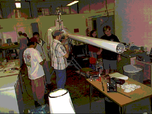
    
    
    Team 2 [Lenski] Final Installations: Tail Boom Mounting (Section 6, pg 19) Attached tail boom to helicopter, connecting mounting plate (#0078) to the airframe and the upper supports (#BA08,BA09) to the tail boom. Adjusted upper and lower support to the specified lengths. Blue loctite the bolts (#0396) on the forward mounting bolts. ***Further work pending. Teams 2 and 3 [Lenski] (working on team 3 assignments) Final Installations: Cabin to Airframe (Section 6, pg13) Previously skipped due to difficulty: Attached collective panel (#0328) and cover to the cabin, thus completing assembly. Optional Accessory: Engine Information System Drilled hole in top for low rpm horn. Deviations: First attempt to drill hole for alarm didn't work and second hole was necessary. ***Further work pending. Final Installations: Console Covers and Instrument Box (Section 6, pg 7) Finished installation Deviations: ABS Avionics Bay Cover (#0330) was replaced with cover that came with radios.. Final Installations: Instrument Panel (Section 6, pg 21) Airspeed Indicator (knots) instead of Airspeed Indicator (mph) (#0643) was attached to Instrument Panel (#0331). Compass (#0641), Altimeter (#0644), Vertical Speed Indicator (#0645) and the Exhaust Gas Temperature Gauge (#0647) were attached to Instrument Panel (#0331). ***Further work pending due to lack of nuts (#0454). Deviations: Sanded Instrument panel (#0331) so Altimeter (#0644) and Vertical Speed Indicator (#0645) would fit. Final Installations: Console Covers and Instrument Box (Section 6, pg 8) The installation was completed: The Pedals (#0141 and #0142) bolt holes were tapped to fit bolt (#0367). The two anti-torque console spacer (#0142) were thinned to mount pedals. The two pedal tube plugs (#0265) were installed. 15 Nov 99 Team 1 [Gomeringer] Operation: Attach trim tab. (This belongs in pre-painting prep, but was skipped in the belief that it was preempted by Mast Support modification. Trim tab attached over paint.) 1. The top trailing edge of the horizontal stabilizer #0663 was sanded cleaned with denatured alcohol. 2. The forward 1/2 inch of the trim tab #0714 was cleaned with denatured alcohol. 3. Trim tab was held in place centered across the stabilizer while 1/8" holes were drilled into the stabilizer through the first surface of the fiber glass only. 4. A bead of epoxy adhesive was applied to the trailing edge of the horizontal stabilizer. 5. The trim tab was held in place on the horizontal stabilizer while 9 rivets #0484 were installed in the holes. Final installation: Transmission to airframe. 1. Transmission bolts were removed one by one and the transmission mounting holes were rereamed using a 3/8" drill bit. 2. Transmission was rebolted using 2 bolts #0403 on the left and matching bolts, longer by 0.25", on the right. Final installation: Push pull control rods 1. Parts were collected for the push pull control rod assembly. Team 2 [Lenski] Final Installations: Engine (Section 6, pg14-16) Finished installation: Adjusted main drive belt. Attached and adjusted tension bars (#0133) to transmission.
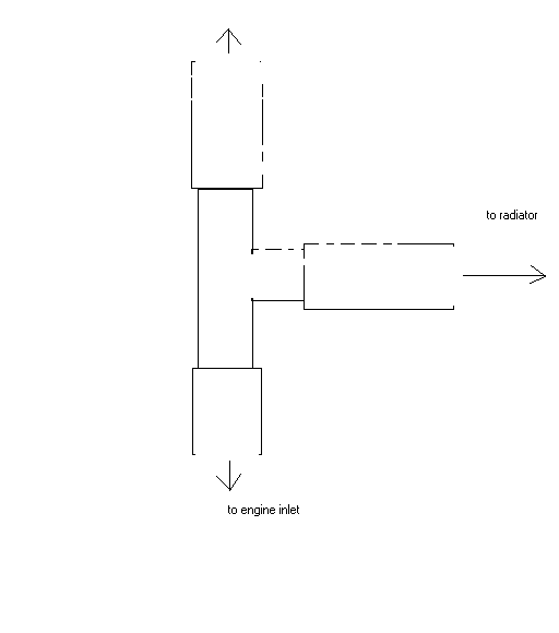
    Final Installations: Tail Boom Mounting (Section 6, pg19) Deviations: The bolt (#0363) stripped the threads on the bolt hole of the tail boom forward Drive Shaft Bearing Retainer (#0036) on left. ***Further work pending. Team 3 [Shackelford] Console assembly: Error discovered: 1. Anti-torque Bellcrank in console frame was found to be on backwards. CORRECTION: Turned it around. Deviation: 2. Pedals came pretapped for 24 threads/inch, while #367 bolts are 1/4x28. CORRECTION: retapped. Instrument panel: Installed following components: engine coolant temperature gauge, dual rotor/engine tachometer, hour meter, and ignition switch into instrument panel. drilled 5/16'' holes near bottom of instrument panel for optional chip detector lights. Put bulb holders through holes. Cut wire furnished with kit into three 24'' pieces and one 6'' piece. Wires soldered to ends of bulb holder per chip detector kit schematic. 17 Nov 99 Team 1 [Othman] Final assembly: Push Pull Control Rods 1. Collective riser block (#0153) was assembled to console opening with 2 washers (#0474), 2 washers (#0473), a bolt (#0380), a nut (#0456) and a spacer (#0204). The spacer was lubricated with white lithium grease prior to the installation. 2. 3 push pull rods (#0165) were attached onto the control rod-ends on lower control yoke. Each rod was secured with a bolt (#0362), 2 2 washers (#0472) and a nut (#0455). The nuts face the cabin. The same 3 push pull rods were attached to the upper control rod-ends in the same manner. 3. It was then discovered that the collective riser block (#0153) was not pivoting freely about the spacer (#0204). The riser block was disassembled for the purpose of enlarging the hole. The correct drill bit for this operation could not be found, and it was put off. Mast Support modification: 1. Blade trim tabs (MS03) and horizontal stabilizer vortex generators (MS04) drawn by A. Katz. 2. 2 tabs (MS03) and 1 vortex generator produced from 0.032" 2024 T3 Al sheet by G. Weeks. 3. The 2 trim tabs (MS03) were treated with clear enamel and let dry. Team 2' (Lenski & Hutson) [Lenski] Final Installations: Tail Boom Mounting (Section 6, pg19) Finished installation: Fixed previously stripped threads (see 15 Nov) with helicoil. Slid turtle deck onto tail-boom. This required that bolts in rear tail boom bearing #0572 be temporarily removed, then reinstalled. Deviations: Enlarged the tail-boom hole in the turtle-deck to allow the boom to slide through. Rubber trim aroungd hole removed & reinstalled with contact cement. Modified the mast opening in the turtle-deck to allow for the mast tilt. Rubber trim partly separated and reattached with contact cement. Tie holding wires in tail-boom broke and was replaced. Hole misaligned #0036 bushing and tail boom and was fixed. Team 3 [Jones] Final installation: Console frame. Installed and adjusted pedals. Final installation: Instrument panel (Jones, Kornegay, Shackelford) Installed 3 switches into instrument panel Replaced 3 switch blanks with automotive rocker switches - checked for connection to determine position. Sanded holes in instrument panel for automotive switches to fit. Connected wires to gauges as instructed on pg. 6.21 step 2. Connected to main harness. Tubes for pitot-static system cut from #0538 and installed. Optional Equipment: Engine Information System (EIS) Cut out and sanded opening for EIS on front side of housing provided. Cut patch from excess material acquired from previous step to repair unused hole on top of housing - secured with 5 min epoxy. Trimmed excess edges on back and front of cover for proper fit on top of instrument box. Spray painted cover gray - needs another coat after it dries. 19 Nov 99 Team 1 [Othman] "Mast-Support" Modification: Trim Tabs on the Main Rotor Blades & Vortex Generators on horizontal stabilizer. 1. Trim tab location (26-3/4 inches from the trailing edge of the blade tip) was marked on both main-rotor blades. 2. Area of top surface of each blade to be covered by the tabs was taped around, then sanded to remove paint. 3. The location of the rivets on the trim tabs were marked and drilled through both tabs together with 1/8" drill bit. 4. Since type of rivets has not been decided yet, the trim tabs were only bonded with epoxy onto the main rotor blade. Final Assembly: Push Pull Control Rods The hole in the collective riser block (#0153) was reamed so that the spacer (#0204) could slide freely in. The push-pull control rods assembly was reinstalled as reported 17 Nov. Team 2' (Lenski & Hutson) [Lenski] Final Installations: Cooling System Plumbing (Section 6, pg27-28) 1. Collected parts. 2. Trimmed hoses. 2. Attached hoses #0694 (left and right), #0508 as specified. Deviations: Engine inlet bends 90 deg upwards. Helicopter instructions show it horizontal. Team 3' (Jones, Kornegay, Shackelford) [Jones] Pilot Seat Assembly * Pilot Seat constructed according to section 6 page 31 -- 5 min. epoxy used to attack washers and bolts per instructions. * Need more black seat trim - not enough to attach top of upholstery to seat * Seat not mounted on console (step 5) pending completion of wiring in console. Washers and knobs (4) placed on screws on bottom of seat until installation. All parts used Optional Engine Information System (EIS) * 2nd coat of paint applied to EIS housing (by A. Katz). * Low rpm horn placed in hole on top of EIS housing. * Mounted EIS to housing with supplied screws, washers, and nuts, secured with loctite 242. * Replaced one amber rocker switch in instrument panel with switch in EIS package. * Low rpm horn wired to main harness but HNPOS wire was cut because it could not reach new location on EIS housing, needs to be lengthened. -need wire and connectors (not supplied) to accomplish this * Cable A and Cable B plugged to back of EIS per instructions. * Mounted EIS housing to instrument box with supplied screws, washers, and nuts, secured with loctite 242. 22 Nov 99 Team 1 [Othman] Tabs & vortex generators for horizontal stabilizer. Pre-Painting Preparation step: Attaching Trim Tab on Horizontal Stabilizer 1. The trim tab #0714 was removed from the horizontal stabilizer. It had previously been bonded over paint and did not adhere properly. Also, the rivets were not seated. 2. The area on the horizontal stabilizer which mates the trim tab was sanded and paint removed. The trim tab was reattached with 9 rivets (#0484) and plastic welder II epoxy. MS Modification: Vortex Generators on Horizontal Stabilizer 1. Location of the vortex generators was marked. 2. The paint was removed in the area where the vortex generators were to be attached (still in progress). This was first attempted by sanding, paint thinner was later used. Subassembly: Rotor Head & Controls Adjustment barrel #0032, previously damaged and repaired, was found not to be threaded deep enough with left hand thread. An attempt at rethreading resulted in stripping the left hand thread near the end of the barrel. Team 2-1 (wiring) [Kornegay] Damage was noticed on the EIS housing. The EIS display and housing were removed. The housing was repaired using fiberglass and resin. Team 2-2 (plumbing) [Lenski] Final Installations: Cooling System Plumbing (Section 6, pp. 27-28) Defined changes to accomodate modified outlet (see 19 Nov) and made list of additional parts needed: 8" of 1" radiator hose, one splice & 2 clamps. Final Installations: Wiring & Plumbing (Section 6, pg22) 1. Collected parts. 2. Cut 96" and 68" of fuel line (#0538) and routed as specified. 3. Installed fuel shut off valve (#0626), primer tee (#0527), primer (#0627), and primer hose (#0531). Parts in required parts list that are missing: 1. #0359 (X3) Bolt 2. #0367 (X2) Bolt 3. #0371 (X4) Bolt 4. #0472 (X2) Washer 5. #0559 (X5) Clamp **missing parts not needed for installation. Team 3 [Jones] Windshields Assembly * Parts were gathered for the assembly - the tee mount brace (#0160) which was previously fit and drilled, could not be found. * A replacement tee mount brace (#0160) was made from 0.119 in. thick aluminum and is 2 3/4" long, and 0.87" wide at one end and 0.71" wide on the other. Two 3/16 holes were drilled in the brace. * Pilot holes were increased to 3/16" per step 1. * the right end of the tee was sanded for a proper fit. Tee bar loosely attached using screws, washers, and nuts per step 2 and figures 30 and 31. * The headlight mount was not installed (step 3) pending completion of wiring in console. * Tee bar and windshield "groove" on cabin was lined with double sided windshield tape where top two windshield will be installed (part of step 4). Pedals One bolt stripped the threads in the right pedal. One other thread in right pedal and 2 in left pedal suspect because all were threaded for 28 thread pitch on top of preexisting 24. All 4 threads to be repaired wit helicoils. Holes in right pedal (2) drilled out and rethreaded with 5/16"x28 tap. 1/4" & helicoils inserted. The helicoils were screwed too far, and bolts could not reach helicoils. 2 additional helicoils inserted in same hole but failed to hold down the pedal. 4 additional helicoils ordered for further repairs 29 Nov 99 Team 1 [Othman] Modification: Vortex Generator on Horizontal Stabilizer 1. Thinner was used to remove paint from the location of the vortex generators on the top surface of the horizontal stabilizer. paint removal was completed by sanding. 2. Vortex generators (2) was attached to the horizontal stabilizer with epoxy (plastic welder II) and (5 each) 1/8 inch aluminum pull rivets. Modification: Trim Tabs on the Main Rotor Blades (1 each) 5 rivet holes were countersunk on each tab. Structural rivets (steel shank) were used in the holes at the edges of the trim tab (2 per tab) and screws were set with epoxy (plastic welder II) in the remaining holes (3 per tab). Team 2-1 (wiring) [Kornegay] (overdue) Team 2-2 (plumbing) [Lenski] Final Installations: Cooling System Plumbing (Section 6, pg27-28) Finished as follows: 1. Added 8" of 1" radiator hose connecting hoses (#0508) and (#0694) with one splice and 2 clamps. 2. Placed hose tee (#0523) directly above the engine inlet oriented as shown.
    To coolant bottle
    Final Installations: Wiring & Plumbing (Section 6, pg22) 1. Adjusted fuel lines to obtain clearance from moving parts while cyclic cover was aligned. 2. Routed main wire harness from backside of fire wall up left side of console. 3. Mounted oil tank (#0334) using bolt (#0361), washer (#0478), and lock washer (#0449) to fire wall and attached 1.5" length of hose (#0539) using 2 clamps (#0517). 4. Attached oil filter (#0661) to end of previously attached hose using clamp (#0517). 5. Attached 51.5" of hose (#0539) to end of oil filter (#0661) using clamp (#0517). Skipped steps: 1. Wiring steps 5 thru 7 pending. Team 3 [Hutson] Pedals - Right pedal threads (including helicoils) cleaned and pedal installed with 1.5x0.25x28 bolts (by Dr. Weeks). Windshields - The right tip of windshield tee and adjoining cabin were sanded for fit. The two cabin hinges #109 and #111 were removed and temporarily installed inside the cabin so as not to obstruct corner of windshield. The left upper windshields, #318 was temporarily held in place with office clips and masking tape (one at a time). Windshield edge position was marked with masking tape to fit groove on cabin and overlap the double sided tape (#341) on the winshield tee. The excess was then cut with snips, the edges were sanded, and the tape was removed. The same procedure was repeated for the right upper windshield #316. Both upper winshields were temporarily taped in place with masking tape for storage until next class. 01 Dec 99 Missing parts produced: Retaining washers #0014 Two that were missing from kit produced from circular steel bar (by G. Weeks). Replacement parts placed in top position of the blade cones. Team 1 [Othman] Modification: Vortex Generator on Horizontal Stabilizer The horizontal stabilizer top surface was touched up with white spray paint (enamel). Final Installations: Tail Assembly Installation (p. 6-32) 1. Light coat of white lithium grease was applied to the inside of the tail rotor drive shaft spline coupler. The tail rotor gearbox was slipped into position and the tail rotor cable routed through the cutout in the bottom of the mounting plate as shown in Figure 120. The 4 mounting holes in the tail boom were aligned and secured to the gearbox with 8 bolts #0387 and 8 washers #0473. Some of the mounting holes had to be enlarged to allow the bolts to engage. Safety wire has not been applied yet. 2. The tail rotor cable was secured as shown in Figure 120, detail B. 3. Rod end #0597 was installed at the end of the cable and attached to the anti torque bellcrank #0115 with a #0362 bolt, 4 #0472 washers and a #0455 nut per Figure 120, Detail A. 4. A bead of clear silicone was applied along the edges of the horizontal stabilizer. The winglets were mounted to the tips of the horizontal stabilizer with 4 #0548 screws, which were secured with Loctite #242. 5. The vertical stabilizer was mounted to the tail rotor gear box with 4 #0477 washers, 2 vertical stabilizer mounting plates #0273, 4 #0473 washers, and 2 #0389 bolts. Team 2-1 (wiring) [Kornegay] EIS was re-installed in the EIS housing. EIS housing re-installed onto the instement box. Wiring for the stick grip buttons was extended through the console Wire used to extend button positive ground green green black black red black blue red green red green black cooley hat positive common ground white. up red down green indent right black indent left not extended through console all wires were grouped by button and labled with masking tape 9 pin D connector was installed on the wires for the cooley hat to be pluged into the EIS wiring to work the "next/ack", "previous", and "display" buttons. button cooley hat position wire next/ack up red previous down green display indent right black white wire for cooley hat goes to ground. Team 2-2 (plumbing) [Lenski] Final Installations: Wiring, Plumbing, & Schematics (pp. 6.22-26A) 1. Riveted battery box left side (#0067), right side (#0256) and tray brace (#0258) and battery box tray (#0257) to form battery box. 2. Cut and glued: a. 4 1" X 1/2" foam (#0339) pieces to front and rear corners of the battery box. b. 2 4" X 1" foam (#0340) pieces to bottom of battery box per Figure 88 (p. 6.25). c. 2 1" X 1" foam (#0340) pieces to side battery plate just below the lip and centered. 3. Attached starter relay and regulator rectifier to bottom of battery box using 2 bolts (#0364), 3 washers (#0473), 3 nuts (#0456), and 1 bolt (#0364) as shown in figure 87 (p. 6.25). 4. Mounted battery box to fire wall using 4 bolts (#0367), 4 nuts (#0456), 4 washers (#0473), and 4 large flat washers (#0477). 5. Connected 57" red cable to inboard terminal on the starter relay and routed the cable along frame and connected to starter using washer (#0450) and nut (#0461). 6. Connected 12" red cable to outboard terminal of starter. 7. Connected IDNST wire on the wire harness to the starter relay. Team 3 [Hutson] Windshield Installation (pp. 6.9-11) Sanded edges of top 2 windshields with Dremmel tool. Tried to temporarily attach headlight mount #677 per step 3 (p. 6.9), but double sided tape would not hold because curvature of #677 & cabin do not match. Masking tape was used instead. Applied double sided tape #341 to the windshield tee, cabin and headlight mount for installation of lower windshields. Temporarily taped (masking) lower windshields in place and marked for trimming. Trimmed excess with snips and sanded edges. Bolt #549 holding tee mount brace #160 to cabin removed and replaced going through top windshield trim. Drilled 3/16 inch holes in cabin using trim as template and placed gleco in each hole (top trim drilled and glecoed, front Tee partially drilled and glecoed). 06 Dec 99 Team 1 [Othman] Final Installation: Tail Assembly 1. The vertical stabilizer was removed from the aircraft and safety wire was installed on the 8 bolts (#0387) that attach the tail rotor gearbox to the tail boom assembly. 2. The horizontal stabilizer was sandwiched between the top mounting plate #0098 and bottom mounting plate #0088 and secured with 4 #0362 bolts, 8 #0472 washers, and 4 #0459 nuts. 3. The horizontal stabilizer was set on the mounting spuds of the vertical stabilizer with 2 #0364 bolts and 2 #0473 washers. Blue Loctite #242 was applied on the bolts prior to installation. 4. The stabilizer assembly was remounted to the tail rotor gearbox. The 4 attaching bolts (#389) were secured with safety wire. Final Installation: Gear Fairing Installation 1. Parts were collected. 2. The legs of the landing gear were scratched inside and outside using a long straight bar. The scratch marks were traced with a marker. Team 2 [Lenski] Final Installations: Wiring, Plumbing & Schematics (pp. 6.22-26A) 1. Routed wiring harness, oil lines and fuel lines to the joint ahead of the collective. 2. Routed oil and primer line up airframe toward engine. 3. Routed the fuel line and wiring harness along airframe toward the rear of the aircraft. 4. Mounted fuel pump with 2 bolts (#0377), 2 washers (#0473), and 2 nuts (#0456) as shown in fig. 89, p. 25. 5. Cut 2" off end of fuel line and connected fuel filter using 2 clamps (#0517). 6. Connected fuel line to inlet of the fuel pump using clamp (#0517) as shown in fig. 89, p. 25. 7. Connected the oil line to the oil pump using clamp (#0517) as shown in fig. 90, p. 25. 8. Cut tach sender wires in transmission to 6" and installed female pins. 9. Attached tach wires to 3 pin connector and optional chip detector kit for main and tail transmission as shown in fig. 84, p. 23. 10. Installed 3 pin connector on tail boom harness and connected it to the main harness. 11. Connected the engine plugs to the main harness. 12. Secured the wiring harness, tail rotor cable, and starter cable to the tail boom support with tie wraps (#0423). 13. Routed wires EGT1,EGT4, EGT5, EGT8 from main harness up vertical frame support as shown in fig. 93, p. 26. 14. Routed EGT probe lead wires with a loop for slack along the frame just below transmission. 15. Cut 4 1" pieces of heat shrink (#0535) and slipped over each wire and connected one probe's white to EGT4, black to EGT5 and the other probe's white to EGT1, black to EGT8. 16. Applied heat to shrink wrap and tie wrapped (#0423) to the front of the tube. 17. Connected the four pin navigation light harness to the main harness and routed one loop to each front gear leg securing with tape as shown in fig. 94, p. 26. 18. Drilled 0.5" hole through each front gear leg saddle as shown in fig. 95, p. 26 and pushed wire through the front of the skid. 19. Mounted throttle Correlator to airframe per section 5, fig 33. p. 5.18, using bolt (#0384), 2 washers (#0473) and washer (#0453). 20. Connected Correlator push rod to collective throttle rod using bolt (#0361), 2 washers (#0472), and nut (#0455). Skipped Steps: 1. Step 21, previously fabricated heat shield around bundle (see fig. 91, p. 25.) is missing. 2. Steps 28 through 33 skipped due to missing parts: (#0449) Lock Washer (2) (#0359) Bolt (3) Heat shielding (made of heat sheet material) applied to the frame in places shown in Figs. 21. 22. p. 4.4 (by G. Weeks). Safety wired heat shields to frame. Team 3 Pilot Seat - Attached seat upholstery to top edge of seat using supplementary seat trim. Windshields - Completed drilling 3/16 inch holes for cabin trim. One predrilled hole of bottom trim was not properly aligned, so new hole (3/16") drilled inboard of the existing one and trim then attached to cabin using existing bolts. Door hinges were remounted on outside of cabin. Center cabin trim drilled with 3/16 inch bit at ends to put hinge bolt through trim as well. Touch-up trimming with Dremmel done on lower left windshield, which was then installed using #549 bolts through the trim strips, except the horizontal center trim. Nuts secured with #472 washers, and #459 nuts, but not torqued yet. Replacement pitch links (2) manufactured from steel turnbuckle barrels MS21252-5L by cutting them off to 3.5" (by G. Weeks). 07 Dec 99 New pitch links installed in rotor head. On the blade cone side, replaced #268 1/8" spcaer on nut side by two 1/16" washers. Left nuts untightened. (by A. Katz). 08 Dec 99 Team 1 Final Installation: Gear Fairing Installation 1. Front fairings were wrapped around the front legs, oriented so that the tie down tab protruded through the large hole in the fairings. The edge of each fairing was slipped under the rear flange. The fairing were temporary glecoed together. 2. A 2X4 wood with notches cut for the skids was used to hold the skids from spreading. With the 2x4 placed over the landing gear laterally near the ground handling wheel brackets, the rear leg cross brace was unbolted and the rear fairings were installed the wrapped around the rear legs with the cross brace attachments portruding through the holes. Then leg cross brace was reinstalled. The fairings were temporarily glecoed together. Could not rivet the fairings together because of shortage of rivets. 3. The mounting holes on the front left fairing were aligned with the scratch line in the leg. 3/16" holes were drilled through the leg using the pilot holes in the fairing as a template. The fairing was secured to the leg with 2 #0515 screws, 4 #0481 cup washers, 4 #0618 O-rings, and 2 #0458 nuts. This procedure delayed for other fairing pending replacement of glecoes with rivets. Team 2 Final Installations: Wiring, Plumbing & Schematics (pp. 6.22-26A) 1. Replaced jet needle, needle jet, and main jet in each of 2 carburetors as specified for the optional power enhancement package. 2. Attached carburetors on the engine as directed by the Rotax operator's manual and connected the throttle and injector cables. 3. Cut 11" primer hose (#0536) and connected primer nipples on carburetors. 4. Inserted primer tee (#0526) in center of 11" primer hose and previous primer hose from the cabin. 5. Safety wired primer hose connections. 6. Cut 16.5" fuel hose (#0538) and connected left carburetor to fuel pump securing with clamps (#0517). 7. Cut 18" fuel hose (#0538) and connected right carburetor to fuel pump, securing with clamps (#0517). 8. Cut 16" fuel hose (#0538) and connected vacuum pulse port on fuel pump to crankcase vacuum port on engine securing with clamps (#0517). Skipped Steps: 1. Step 38, battery not ready. Low Rotor Micro Switch (p. 6.29) Installed switch as specified. Deviations: 1. Micro switch cover (#0632) broke and was left out. Air Filter (p. 6.30) 1. Collected parts. 2. Trimmed air filter housing (#0333) to the scribe lines and enlarged three 1/8" holes to 3/16". 3. Placed filter (#0425) into housing and drilled the three 3/16" holes through the filter. 4. Glued air filter to housing and modified #478 washers as illustrated in Figs 115, 117. Team 3 [Hutson] Windshield installation - Continued to install windshields using bolt #549, washer #472, and nut #459. Some holes in trim were slightly enlarged and minor sanding of windshields done for proper fit. Discrepancies: 1. Holes in the windshield tee had been drilled to a 3/16" diameter all the way through instead of 1/8 part way. Sheet metal screws #514 cannot hold. Larger screws now needed to complete windshield trim installation. 2. Headlight mount #677 did not fit under bottom piece of windshield trim leaving an unsealed gap between the cabin and headlight mount. Solution to be determined. Status: All four windshield pieces are attached. All windshield trim pieces are attached except center piece. All trim pieces held with nuts except on the windshield tee. Nuts for cabin trim are untorqued.
    24 Dec 99 Mast Support mock-up (A. Katz) A mockup of the Mast Support arms was installed. Each arm was made of a 1/2" plastic tube (representing a 1/2" steel tube) with 2 1/4x28 nuts inserted at both ends (to be welded). The top nut is left handed (AN315-4L) and the bottom nut is right handed (AN315-4). The top rod-end is a 1/4" bore ball MB-4. The bottom rod-end is AN165-32RS (flat, 1/4"). Rod ends are secured with jam-nuts (AN316-4L and AN316-4). The top rod-ends were attached to the Mast Support fitting (MS3) with two bolts (1/4x28 grip 4.063) AN4-44A. On the bottom, the rear attach points were created by changing the 2 #394 bolts attaching the tail boom to the frame with 2 rod-ends (MD46-15M, bore = 1/4", male 3/8x24 RH) with jam nuts (AN316-6). On the front, forks (AN161-32RS) were attached to the frame through 1/4" holes drilled in the top front outside webs. Washers ground on one side where placed on top of the webs. Tubes were individually fit to size and marked. Ordinary nuts wre temporarily used in place of the lock nuts intended to permanently secure the Mast Support. A shortage of nuts and washers prevented temporary tightening of all connections. Proper torque and blue locktite needs to be applied to the 2 MD46-15M rod-ends and also to the #396 bolt attaching the top left support of the tail boom to the front of the airframe (which was temporarily removed and reinstalled.)
    05 Jan 00 Mast Support mock-up (A. Katz) All lock nuts replaced with regular nuts and made finger-tight. 06 Jan 00 Mast Support (A. Katz and G. Weeks) Rod ends providing rear lower eyes for attaching support arms were modified: 1. Thread cut all the way to eye. 2. Threaded part cut to 1.00" 3. Ball ground to housing level. These modifications placed the eyes as close as possible to frame node and eliminated universal joint at botton of support arm, since there is one at the top. Team 1 Final Installation: Gear Fairing Installation 1. Clecos were removed and structural rivets (supplied by Dr. Weeks) were installed one at a time per figure 125 (p 6.33). The left leg fairings attached to the front and rear left legs as follows: 2. The holes on the fairing were aligned with the scratch line in the leg. Drilled 3/16" holes through the leg on both sides. 3. The fairing was secured with a #515 screw with a cup washer (#0481) and 2 O'rings (#0618), one under the head of the screw and the other under the nut on the inboard side of the fairing, per hole (2 holes per leg). Team 2 [Lenski] Final Installations: Air Filter (p. 6.30) Finished installation 1. Attached 3 bolts (#0357), 3 washers (#0478) and 3 nuts (#0455) to hold air filter (#0425) to the air filter housing (#0333). 2. Glued silencer (#0277) to top of filter using MA300. 3. Glued foam strip (#0340) to air filter housing (#0333) using Armstrong 520 contact cement as shown in fig. 114. 4. Enlarged 4 pilot holes to 15/64, located just below the filter. 5. Inserted the float bowl pressure equalization tubes from the carburetors into the 15/64 holes as shown in fig. 115. 6. Opened throttle until throttle slides were at the top of the carburetor opening and synchronized carburetors as shown in fig. 117a. Final Installations: Console Covers and Instrument Box (p 6.7) Riveted 6 anchor nuts (#0471) onto console. Carpet (p6.8) Attached pedals to the tail rotor cable according to figure 6-11. Team 3 [Jones] Windshields: The hole was enlarged in the front windshield trim so the holes in the trim and tee would match. 3/8 self-tapping screws were used to attach windshield trim to tee in place of #514 because the holes were drilled too large. All nuts used to attach windshield were tightened until cabin started to crush. Washer #472 was removed from screw used to attach tee bar mount to cabin because not enough threads were showing for nut to hold. The windshields are complete. Cabin trim: Lower left and right, and upper left cabin trim was marked to be cut. Left lower cabin trim is in the process of being cut and sanded to fit. 11 Jan 00 Team 1 Final Installation: Gear fairing Installation The fairings on left legs attached in the same manner as the fairings on the right legs were during the previous session. The cross brace was adjusted to make the skids parallel to each other. Team 2 [Lenski] Final Installations: Cabin to Airframe (p. 6.13) Set instrument box onto cabin and installed 6 anchor nuts (#0471). Final Installations: Wiring, Plumbing, & Schematics (pp. 6.22-26A) 1. Ridged heat shield (#0309) attached to gas tank using 4 bolts (#0359) and 4 lock washers (#0449). 2. Glued four 1" pieces of heat shield over bolt heads on ridged heat shield (#0309). 3. Two sight gauge elbows (#0262) pushed through firewall. 4. Cut 2" and 9" fuel hose (#0538) and attached to upper and lower sight gauge (#0262), respectively, using clamp (#0517). 5. Fuel tank was attached to airframe with 2 loop clamps (#0559), 2 bolts (#0437) and 2 lock washers (#0450). Team 3 [Hutson] Carpeting installation Remaining carpet edges folded under for clean look and glued down with contact cement. Carpet installation now complete. Cabin trim final installation All door trim pieces cut then sanded 1/2 inch from topmost surface. Left lower door trim #327 not large enough to cover cabin completely. Cabin edge not covered by this will be painted black. Screw holes (4) marked on each piece and drilled using 3/16" bit. 13 Jan 00 Team 1 [Gomeringer] Modification: Mast support. Changes to previous mockup implemented: 1. Two steel yoke ends, plain 5/16 (6414K11) for the bottom of the aft support arms threaded using a 5/16 -24 die. 2. Two 5/16" steel turnbuckle barrels (MS21251-10L) sowed in two. The right hand thread together with the center section to serve as an "extended nut" to be welded into bottom of rear support arms. 3. Four 1/4" steel turnbuckle barrels (MS21251-8L) sawed in two. Left hand thread together with center section to serve as "extended nuts" to be welded into top of all four support arms. Two of the right hand thread sections to serve as "extended nuts" and to be welded into bottom of front support arms. 4 Two AN3B-4A 1/4" eyebolts drilled to increase eye to 1/4". These eyes attached to AN161-32RS clevises to serve at bottom of front arms with 2 1/4" washers (AN970-4) and a AN4-7A bolt (1/4x28, grip= 7/16) and a matching nut (MS20365-428). Eyebolts temporarily attached to holes in front frame webs with 1/4" (MS20365-428) nuts. Team 2 [Lenski] Final Installations: Wiring, Plumbing, & Schematics (pp. 6.22-26A) 1. Had to cut a longer piece of fuel hose (#0538) for upper elbow sight gauge (#0262). 2. Wired Landing Light (#0633) to spot lines. Missing pieces: 1. Did not have enough oil line. Cabin to Airframe (p. 6.8) 1. Mounted the instrument box to the console using 6 bolts (#0357), 6 washers (#0472) and 6 nuts (#0455). Wiring Instrument Panel (Schematics, pp. 6.23-24) 1.Wired gages on instrument panel as shown in schematics on pg 23-24. Pitot & Landing Light (p. 6.12) 1. Drilled 3/16 holes as shown in fig 50 (p. 6.12). Modified: 1. Attached anchor nuts (#0471) to the aircraft. 2. Secured landing light retainer (#0120) with 2 of 4 aircraft screws (#0539). Other 2 screws pending. Team 3 [Hutson] Cabin trim installation Door installation Additional sanding done to trim for better fit. Trim mounts #77 (4 per trim piece) and srews #555 (4 per trim piece) attached to all cabin trim. Trim glued in place with MA300 adhesive and clamped down, but did not remain in place on the cabin. Additional attempts failed. Left lower trim piece reglued and left clamped in place. All parts listed in sec. 6, p. 36 obtained with exception of nuts #459 and washers #472 and #475 (not found on parts board). 18 Jan 00 Team 1 Sub-assembly: Rotor Head & Controls Slippage marks were applied to #0470 nut on the upper control rod attachment and to the to #0456 and #0457 nuts on the adjustment barrel assemblies and on the pitch arm assembliesby with a permanent marker. Modification: Mast Support 1. Boom tube mounting plate #0078 was ground in two places to relieve interference with the aft support arms. The ground surfaces were smoothed with a Dremel tool. 2. A mock-up of the 4 mast support barrel arms using plastic tube instead of steel tube and all the actual "extended nuts" made of halves of steel turnbuckle barrels was completed and installed. All parts were marked. The barrel arm mock-ups were then taken apart in preparation for manufacturing the actual barrel arms. Tail boom mounting Blue locktite and torque applied to the #396 bolt attaching the top left support of the tail boom to the front of the airframe (which was temporarily removed and reinstalled on 24 Dec.) Team 2 [Lenski] Final Installations: Wiring, Plumbing, & Schematics (pp. 6.22-26A) 1. Attached oil line using two clamps (#0517) on vent tube. Wiring Instrument Panel (Schematics, pp. 6.23-24) 1. Soldered extension to HNPOS wire to reach sender. 2. Wired the cylinder head temperature probes to the engine information system (EIS): a) Removed 2 nuts from the cylinder head and placed the probes under the nuts and retorqued to Rotax specifications. b) Routed wires from EIS to engine and connected the wires to the probes. 3. Chip detection lights wired to main harness. 4. EIS warning light installed. Pitot & Landing Light (p. 6.12) Finished landing light installation. 1. Secured landing light retainer (#0120) using 2 additional aircraft screws (#0539). Navigation Lights (p. 6.34) rear light. 1. Routed tail navigation light wires down through the vertical stabilizer. 2. Connected navigation light wires to the light using 2 butt connectors (#0530) 3. Screwed light fixture to vertical stabilizer. 4. Injected silicon into tail skid mounting hole in the vertical stabilizer. 5. Inserted skid tube and secured with bolt (#0370), 2 washers (#0473), and a nut (#0456). Team 3 [Shackelford] Cabin Trim Removed the lower left side trim from the cabin after using MA300 glue on the trim mounts. One of the trim mounts did not stick to the cabin. Glued the loose trim mount back on to the cabin and clamped it down. Put glue around the other three trim mounts as instructed. Then glued the upper and lower right side trim mounts to the cabin and clamped in place. Left clamped. Navigation Lights (fwd) For both skids of the landing gear: Pulled the wire loop out from the front of the skid and cut. Trimmed the wires so that 3 inches of each extended from the skid. Stripped 1/4" of insulation from each wire. Trimmed the wires on the pigtail 2" and stripped the insulation 1/4". Connected the pigtails to the skid wires with a cap type connector supplied with the kit. Pulled the nav light pigtail through the light mount to insert the bulb into the socket. Slipped the assembly into the end of the skid. Drilled a 3/16" holes as instructed, but used self tapping screws instead of rivets. The end plugs for the aft end of the skids were inserted and secured with rivets. 20 Jan 00 Team 1 [Gomeringer] Modification: Mast Support 1. The four steel tube parts of the support arm barrels were marked on a 5/8" steel tube (R5/8x058-41) using the plastic tubes employed in the mock-up. The tube parts were then cut with a pipe cutter. 2. The "extended nuts" made from halves of steel turnbuckle barrels that were previously marked as to location and depth of insertion, were now welded in place. The welding was performed (at no cost) by the muffler shop in Northport. The top "nut" of each barrel is the left thread half of a 1/4" steel barrel (MS21251-8L). The bottom "nuts" were all right hand thread halves of steel turnbuckle barrels, in the front 1/4" (MS21251-8L) and in the rear 5/16" (MS21251-10L). 3. After welding the nuts were straightened while appropriate bolts filled the nuts. 5. The entire mast support was assembled to assure proper fitting of all parts. It was disassembled and each of the the welds on support arms was cleaned with a wire brush. Team 2 [Lenski] Wiring Instrument Panel (Schematics, pp. 6.23-24) 1. Connected EIS, EGT to main wiring harness. 2. Connected green button on cyclic control stick to landing light. 3. Connected black button on cyclic control stick to navigation lights. 4. Connected main circuit breaker. Cabin Trim (pp. 6.35) 1. Scraped glue off screw mounts. 2. Applied small amount of MA300 on screw mounts and clamped at each screw as per figure 133. Team 3 [Shackelford] Cabin Trim Unclamped the lower and upper right side trims. Put MA300 glue around the trim amounts as instructed. Additional sanding was done to the trims for better fit. Glued the upper left side trim mounts to the cabin and clamped in place. Left clamped. Door Installation Collected most of the parts needed. Removed the left hinge and screwed it on from inside the cabin. Started with the right door trim for sizing. Sanded the door trim's edge to fit in place. Taped around the carpet. Then taped the door trim in place to cabin. Marked 4 line up points around the door. Marked the locations of the door hinge inserts #0722. One insert was sanded for a better fit. 22 Jan 00 Mast support: The 4 steel mast support arm barrels were primed and painted. (by A. Katz) 25 Jan 00 Team 1 Modification: Mast Support The mast support was permanently assembled in place:
    1. Blue locktite was applied to the two reworked MD46-15M rod-ends at the aft bottom attachment where they screw into the airframe. 3. The mast support arm barrels were reassembled as on 20 Jan The top of each barrel mates a 1/4" bore ball MB-4 rod end. At the bottom, each front arm mates a clevis (AN161-32RS), and each rear barrel mates a 5/16" steel yoke end (6414K11) that had been threaded with a 24 die. 4. The top rod-ends were attached to the Mast Support fitting with two bolts (1/4x28 grip 4.063) AN4-44A with 3 1/4" washers for the aft arms and 2 1/4" washers on each side for the forward arms and secured with nylock nuts (1/4" X 28). 5. On the front bottom rod ends, the AN3B-4A 1/4" eyebolts (with eye drilled 1/4") were attached to the frame with nylock nuts (1/4" X 28). Two 1/4" washers were ground on one side and placed on top and bottom of the webs. 6. The 1/4" bolts attaching the bottom rear clevises to the reworked rodends were secured with 1/4x28 nylock nuts. Rework: Friction in Collective Problem: Collective subject to irregular friction even with friction off. Collective stick was disconnected from friction system, and it was verified that it moved freely. The nylock nut(#0455) at the collective torque bar was loosened, and the friction system reconnected. Now collective moves smoothly. Team 2 [Lenski] Wiring 1. Bought nipples for EIS fuel flow sending unit. 2. Drilled and cut holes in avionics bay cover for radios (nav-com and transponder). 3. Assisted team#3 in preparing the helicopter doors (refer to Team 3 report for details) Team 3 [Jones] Left and right door trim (729 and 730) where marked where inserts (721 and 722) fit. Carpet in cabin was taped for protection. Left cabin hinge 111 was removed and reconnected on the inside of cabin. Left door trim 729 was sanded to fit. Inserts (721 and 722) were bonded to left and right door trim (729 and 730) with structural adhesive by 3M. J-B Weld was used to fill in gaps between door trim and inserts. 27 Jan 00 Team 1 [Gomeringer] Rework of Subassembly: Collective (p. 5.19) 1. Each nylock nut #0460 which attaches to each of the two eye bolts #0545 (Figure 36) was loosened. Each nylock nut #0455 which attaches to each of the two bolts #0359 (Figure 36) was loosened. Each nut (# 456) which attaches to each of the two bolts #0375 (Figure 35) was loosened. This relieved undesired friction in collective. Rigging, Balancing, And Engine Break-in. (p. 7.1) 1. Each main rotor cone was filled with 6 3/4 ounces of Revlube rotor head oil #E0014. 2. Main transmission was filled with 1 quart of Revlube gear lubricant #E0015. Team 2 [Lenski] Wiring Instrument Panel (Schematics, pp. 6.23-24) 1. Mounted the circuit breakers in the avionics bay cover. 2. Wired the power to the circuit breakers from the battery through the master avionics switch. 3. Wired each circuit breaker to its respective device. 4. Wired the EIS fluid temperature wire to the main harness. Team 3 + Lenski [Jones] Doors Holes for the door latches were back drilled through both door trims (729 and 730). Each door trim was taped to cabin with double -sided tape and door glass (731 and 732) was marked for cutting and bonding. Door glass (731 and 732) was cut and sanded. The bonding area on each door glass was scuffed and cleaned with denatured alcohol. 01 Feb 00 Team 1 Final Installation: Battery The battery was filled with acid (UN 2796) and charged in trickle mode (2A). It was then installed in aircraft and (except for tests ofelectrical systems) left with ground terminal disconnected. Rigging, Balancing, And Engine Break-in. (p. 7.1) A tag saying "lubricant installed" was removed from transmission. It was conjectured that putting in a quart of lubricant on 27 Jan may have been unnecessary and that the transmission may contain excess lubricant. The transmission was drained and only one quart of lubricant came out. Team 2 Wiring Instrument Panel (Schematics, pp. 6.23-24) 1. The EIS tach was connected to the main wire harness tach 2. 2. The EIS fuel flow sender unit was attachted to the airframe with two wire ties and spliced into fuel line. 3. Ran ground and power wire to avionics master switch. 4. Started power check with radio attached. Decals Painted Experimental on the right side of the console with black enamel using Wag-Aero stencil. Team 3 [Hutson] Identification - N-number - N6165T - stencil made of poster board and double-sided tape instead of method suggested in Wag-Aero lettering kit. Characters traced from kit (compliant with FAR 45). Stencil put in place at center of top-most left side of turtle deck #674. To be painted next class. Stencil reusable for right side. 03 Feb 00 Team 1 [Gomeringer] Rigging, Balancing, and Engine Break In 1. The main transmission was refilled with the 1 quart of Revlube gear lubricant #E0015 that was drained 01 Feb. 2. The tail rotor gearbox was filled with 3 ounces of Shell SPIRAX-HD 85W-140 gear oil. Team 2 [Lenski, Katz] Wiring Instrument Panel (Schematics, pp. 6.23-24) 1. Outside air temperature probe installed on nose of aircraft and connected to the EIS system. 2. Checked electrical system and verified power supply to landing lights, nav lights, EIS system and radios. 3. Checked that EIS system functions, but no calibration done on any reading. 4. Found com radio in "stuck microphone" condition. This was due to Push To Talk (PTT) switch on grip being normally closed. Problem momentarily open instead normally open momentarily closed. corrected by connecting a 1KOhm resistor and rewiring as shown here. With the PTT fixed, operation of the com radio was verified against a hand held transceiver.
    Team 3 [Hutson] Identification - Aircraft ID numbers painted with black enamel on both sides of turtle deck. 'Experimental' label painted on left side of console. Both markings cleaned of runs and other blemishes. 08 Feb 00 Team 1 Rigging and Balancing: Belt Track & Tension A tool to check the tension in the belt, similar to one shown in figure 9 (p. 7.2) was made of tubes and wires. One tube was put against the drive belt on the right side of the aircraft and centered in the span. The wires were run through to the left side of the aircraft and attached to a second tube to assure an even distribution of load to both wires. A spring scale was attached to the cable and pulled. The belt tension was adjusted so that at 1/2" deflection of the belt, the spring scale read 17 lbs (which is within the specified range of 16-18 lbs). Team 2: [Lenski] Wiring Instrument Panel (Schematics, pp. 6.23-24) 1. Connected static line to encoder and to the static tube. 2. Connected dynamic pressure line to pitot tube. 3. Attached instrument and radio cover. Team 3: (with help from other teams) [Lenski] Door Installation (pp. 6.36-40) 1. Taped left door trim (#0729) to the cabin as shown in figure 138. 2. Gathered supplies: duct tape, masking tape, rags, small wood blocks, and the Devcom adhesive. 3. Applied adhesive to the left door trim(#0729) and aligned glass. 4. Taped glass on both inside and the outside of the cabin, using wood blocks to apply pressure where necessary to avoid bubbles in the glue. 5. Cut door latch support plates (2), door striker plates (2), and the door spring tabs (2) using the provided template and sanded edges smooth. 10 Feb 00 Team 1 Rigging, balancing, and engine break in 1. One gallon of Revlube Coolant #E0021 (green) was mixed with one gallon of distilled water. This was done by filling half of a 1 gallon milk container with the Revlube coolant and then filling the rest of the container with distilled water. The original coolant container, which was then half full, was filled to the top with distilled water and now contains the mixture ready for use. 2. Bolt #0443 in top rear of cylinder head was removed to allow air to escape when the cooling system was filled. 3. The cooling system was filled until coolant began to come out of the hole in the rear of the cylinder head. 4. Bolt #0443 was replaced but not tightened. 5. After the system was filled it began to leak where radiator hose #0508 connects to the radiator. The hose clamp #0696 at this connection was loose. It was tightened and the leak stopped. Console frame and cyclic control (p. 5.13) [rework] 2 bolts #0366, used to install eye bolts #0545 into clevises #0544, were loosened. These bolts were originally over tightened making the cyclic stiff. The manual (p. 5.14, #20) specifies that these bolts should be tightened only until the play was removed. Console frame installation/tail rotor assembly Investigation of the stiffness of the anti-torque pedals is in progress. The pitch links of the tail rotor nlades were removed and reinstalled only lightly tightened to secure parts. Team 2 Team 3 Door Installation Right Door Taped the door to the cabin. Applied adhesive along the edge of glass. Used denatured alcohol with paper towels to wipe off excess glue. Then aligned the glass to the door. Taped glass on both inside and the outside of the cabin, using wood blocks to apply pressure where necessary to avoid bubbles in the glue. Left Door Added more glue along the edge between the glass and door in places where they separated. Used clamps to hold together. Cut a slit in the glass in one place where it buckled. Door Latch Support plates (p. 6.40) Drilled 3/8" hole into center of both door latches. Drilled three 1/8" holes along the edge of both door spring tabs. 15 Feb 00 Team 1 Rigging,Balancing & Engine Break In: Fluids 1. The injection oil reservoir was filled with 3 1/2 quarts of 2 cycle oil. 2. The oil line was squeezed with the bleed screw removed from the oil pump in order to work out air from the line. 3. The bleed screw was reinstalled. 4. The cooling system began to leak again where radiator hose #0508 connects to the radiator. The hose clamp #0696 was tightened again, but the leak persisted. Left aircraft with container under belly scoop to catch the dripping coolant. Attaching the turtle deck (per instructions in Post-painting Preparation) 1. Clecos were applied temporarily in order to attach the turtle deck to the cabin and belly scoop. Team 2: [Kornegay] Worked on tail rotor control stiffness and free play. Stiffness caused by spherical bearings (#7331, 2 per blade) that serve as tail rotor feathering hinges. Free play results from stiffness. Control cable (#428) and control arm (#115) bend before blade pitch starts changing. Loosened bearings by applying grease and cycling. Improvement achieved, but stiffness and free play still there. Team 3: [Jones] (Jones, Shackelford, Lenski) Door Installation (pp. 6.36-40) Right door 1. The door was removed from the Cabin, where it was left for glue to cure. 2. Devcon Plastic Welder (#3851A) was used to bond the portions of the door that had voids, C clamps and clips were used to apply pressure. Left door 1. The edges of the door were sanded until it properly fit flush against the Cabin. 4. Both Door Stricker Plates (made from #0733) were bent 90 deg per Figure 153. 5. Attached upper door hinge (#0110) to Cabin hinge (#0109) with a 10-32 bolt (temporary-see deviations below) and washer (#0472) between #0110 and #0109. 6. Aligned door and used hinge (#0110) as a guide for drilling 2 3/16" holes. After the 2 holes were started, the door was placed on a table to finish the drilling. 7. The upper hinge was attached to the door with 2 bolts (#0728) and two nuts (#0454) as shown in figures 148, 153. 8. The lower door hinge (#0110) was used to guide two 3/16" holes for the lower hinge as shown in figure 152. 9. The lower door hinge (#0110) was attached to the door using two bolts (#0728), two washers (#0472) and two nuts (#0454) as shown in figure 152. 10. The Cabin lower hinge (#0111) was attached to the lower door hinge (#0110) using a 10-32 bolt and washer (#0472) between #0110 and #0111. Deviations: 1. In steps #5 and #10, above, the manual called for a bolt (#0358) and three washers (#0472). However, the bolt was lost and a shorter bolt was used temporarily. 2. In step #7, above, the manual called for two washers (#0472) under the nuts. However, the bolts were too short to accomodate the washers. 17 Feb 00 Team 1 1. About 2/3 gallon of coolant was collected from the leak. Radiator hose #0508 was removed. The radiator was full. The leak had occured where the hose connects to the radiator. It appeared that the radiator hose slipped up as the 2-inch hose clamp #0696 was being tightened. The manual (p. 6.27, #4) warns that this could occur. 2. The end of hose #0508 that connects to the radiator was trimmed by approximately 2/10". 3. The hose (#0508) was reinstalled and the clamp (#0696) was tightened. The cooling system was refilled with a mixture of 50% distilled water and 50% Revlube coolant #E0021. 4. Hose #0509 on the right side of the radiator was inspected. It was found that the 2-inch hose clamp #0696 at this connection was oriented in a way that made it very difficult to tighten. The clamp was loosened and turned counter clockwise by approximately one quarter of a turn and retightened. an amount of coolant leaked while this was accomplished. 5. Some coolant was noticed at the radiator drain plug. To be inspected. 6. A 1/4" hole was drilled at the left bottom corner of the belly scoop to allow coolant collected there from leaks to drain. Tail rotor rework The parts removed while reworking tail rotor control in attempt to achieve easier movement and eliminate free play were tightened and checked for proper torque. These included Nylock nut #0456 which assembles with bolt #0369 and holds on the tail rotor bellcrank arm #0115, 2 Nylock nuts #0456 which connect to 2 bolts #0373 and which attach rod ends #0593, 2 bolts #0364, Nylock nut #0455 which secures the tail rotor cable. Team 2 No activity. Team 3. [Jones] (Jones, Shackelford, Lenski) Right door: The adhesive on the right door was not cured yet. Left door: Two 3/16 holes were drilled in the Cabin for the bottom hinge per figure 152. Both doors: 1. Drilled 3/8 hole in door latches. 2. Bonded latch support plates with Devcon Plastic Welder (#3851A) (instructions call for MA300 but we are out). 3. One of the Door Pivot Rods (#0719) was inserted into one of the door latches (#0720) and removed. When tapping the Door Pivot Rod out, the end was deformed and was sanded so it would later refit into the door latch. 4. The two push fit ball plungers (#0723) were cooled in the freezer and inserted into the two door latches (#0720), which were heated with the heat gun. 5. Two wood blocks were cut to be used as a support between the cabin and the cabin trim in the area where the striker plates will be installed according to figure 151. One block was bonded to the upper area of the right door opening in the cabin using 3M structural adhesive. The block was not bonded on the left side because one of the trim mounts (#0077) came off and was re-bonded with 3M structural adhesive. (The bonding areas on the cabin were sanded and cleaned to insure a good bond.) 22 Feb 00 Team 1 Final Installations: Cooling system plumbing 1. Two 2 in. pieces of seat trim molding were cut and installed with contact cement on the fan shroud next to the coolant hoses to prevent chaffing. Rigging,Balancing & Engine Break In: Fluids 1. The 2-inch hose clamp #0696 on the right side of the radiator was tightened. 2. Coolant was refilled. 3. 8 ounces of 2 cycle oil was mixed with 3 gallons of gasoline to obtain the dilution ratio of 50:1. Team 2 [Kornegay] Sanded the tips of the tail rotor and painted them red. Mounted the identification plate behind the left door with rivets and structural adhesive. Team 3 [Shackelford] Door Installation (pp. 6.36-40) Left door: 1. The edges of the door were sanded for a proper fit against the Cabin. 2. AN525-10R12 screws used for Lower cabin hinge and to attache the lower hinge to cabin (Fig. 152). Right door: 1. The edges of the door were sanded for a proper fit against the Cabin. 2. Aligned door and used hinge (#0108) as a guide for drilling 2 3/16" holes. After the holes were started, the door was placed on a table to finish the drilling. 3. The upper hinge was attached to the door with 2 bolts (#0728) and 2 nuts (#0454) as shown in figures 148, 153. 4. The lower door hinge (#0018) was used to guide two 3/16" holes for the lower hinge as shown in figure 152. 5. Bonded a 1/4" block to the upper area of the door opening in the cabin using 3M structural adhesive shown in figure 151. Door handles (Figure 147): 1. Both Door Pivot Rods(#0719) were sanded on both ends to fit. 2. Drilled 3/32" holes through Handles (#0724) and Rods (#0719) and put Spring Pins .093x.625 (#727) into the holes. 3. Red loctite #262 was put on both screws that were in the handles. 4. Drilled 3/32" holes on one side of both Door Latches (#0720). 24 Feb 00 Left door (Jones, Lenski, Shackelford) [Shackelford] Door Handle and Ramp (Figures 147, 149, & 150) 1. Pushed the Spring Pin .25x.75 (#0725) into the Door Latch Insert (#0721). 2. Marked location of pin slot on the cabin. Made cutout for Latch Ramp (#717) with cutting wheel and hacksaw and drilled 2 3/16" holes through the cabin. 3. Attached the ramp (#0717) to the cabin with screws (#????). (note: the number in the manual was not correct for the screws) 4. Located and marked a pin hole on the Door Pivot Rod (#0719). 5. Drilled 3/32" holes through Door Latch (#0720) and Door Pivot Rod (#0719) 6. Installed the door handle in the door and drove the Spring Pin (#0726) into the hole with hammer. Deviations Removed Left Upper Door Trim (#0325) because attach nuts not secure on cabin Left off the door striker plate and door spring tab. Painting Masked window part of door glass and (#0731) and metal handle and hinge brackets with masking tape and paper. Spray painted the outer edge of the glass white. Right door (Gomeringer, Hutson, Othman) [Gomeringer] 1. Bottom door hinge #0108 was attached to door using 2 bolts #0728 and 2 nylock nuts #0454. 2. Bottom cabin hinge #18 was attached to the cabin using 2 bolts #0358, 6 washers #0472, and 2 nylock nuts #0454 using holes drilled previously. (shown in figure 152) 3. Pushed the Spring Pin .25x.75 (#0725) into the Door Latch Insert (#0721). Used C-clamp to force it in. 4. Marked location of pin slot on the cabin. Made cutout for Latch Ramp (#718) with cutting wheel and hacksaw and drilled 2 3/16" holes through the cabin. 5. The door did not fit, leaving a gap at the bottom. It was removed and the front edges were ground for better fit. The door was then reinstalled. 6. Door latch ramp #0718 was attached with 2 bolts #0728 as shown in figure 150. No loc-tight was used. 7. The right door was again removed because it did not properly line up with the cabin. The hinges #18 and #0108 on the door were removed. The door was lined up and new holes were drilled through the hinges. 8. Door reattached and latch installed by A. Katz and G. Weeks. It still leaves a gap on the bottom. Deviations Left off the door striker plate and door spring tab. Attachment of Turtle deck (Kornegay)[Kornegay] Glecoed the Turtle deck to the cabin and belly pan. Removed each gleco in turn and drilled out #10 hole for the fastener. Riveted anchor nuts MS21042-3 to the cabin (14) and turtle deck (5) with 3/32 x 1/4" rivets (MSP-32). Fastened the turtle deck to the cabin and belly pan with 15 10-32 x 5/8" screws (AN525-10R10). 27 Feb 00 (A. Katz) Installed battery hold down (#259) over battery per figure 86 (p. 6.25) Reglued right door above inges in front where glass separated from frame with Devcon epoxy. Attached with clips and left to dry attached to helicopter. 29 Feb 00 Team Report(Shackelford,Othman)[Othman] Right door: The door was removed from the cabin. Voids were repaired with Devcon Plastic Welder (#3851A) and held with clips to cure. Left door: Several additional coats of white enamel were applied. Team Report (Kornegay)[Kornegay] Adjusted the low rotor rpm switch to not engage with collective down. 05 Mar 00 (A. Katz) 1. Door hinges (4) replaced with AN393-17 pins secured by AN416-2 safety pins. 2. Installed right lower cabin trim (#326). 3. Made cuts in edges of upper door trims (#324 & #325) to make them easier to bend into cabin post shape. Left trim mounts reglued to cabin attached to trim and held in place with C-clamps. 07 Mar 00 (Kornegay)[Kornegay] Right door, Masked with tape, sanded and spray painted with white enamel (2 coats). (Shackelford) [Shackelford] Left door: 1. Glued the Door Latch support plate back on with 5 minute epoxy. 2. Masked window part of door glass with masking tape and paper. Sanded and spray painted the outer edge of the glass with white enamel (one coat). Helicopter weighed and raw data obtained to determine CG location in 3D. Helicopter hoisted up by mast to check balance, and swung in roll & pitch to determine moments of inertia. See Weight and balance report for details. 09 Mar 00 (Katz) Collective stops (p. 7.1): 3 push-pull tubes (#0165) adjusted in length until top teeter block yoke #0027 touches #0038 with the collective all the way down and bottom #0027 almost touches #0029 with the collective up to the top of its slot in the firewall. 14 Mar 00 (Katz, Weeks, A. Darling & entire class) Helicopter moved from UA Campus to FDL hangar at Tuscaloosa Airport. Tail rotor rigging (p. 7.1) performed. 16 Mar 00 (Katz, Weeks & entire class) Collective stops (p. 7.1): Top of collective slot in firewall enlarged slightly by filing with sandpaper on a round wooden handle. (The the collective sleeve plate and friction mechanism was temporarily removed to allow this work, then reinstalled.) Now bottom #0027 touches #0029 with the collective all the way up. Cyclic Rigging (p. 7.1): Left push-pull rod #0165 shortened two turns & right push-pull rod #0165 lengthened two turns. The jam-nuts on all three push pull rods (6) tightened. Blade installation (p. 7.9): Blade A was mounted to cone A and Blade B to cone B per instructions. Blade pitch setting (p. 7.9): With the helicopter on the apron, the side inclination of the mast was measured with an inclinometer and found to be one degree to the left. The blades were placed at azimouth 0 - 180 and the upper control block #0016 was inclined 1 deg left to be perpendicular to the mast. With lateral cyclic held in this position and collective all the way down, the length of the two pitch links was adjusted until the pitch of each blade at the tip was 0.5 deg down relative to the mast. This was verified by placing the template shown on p. 7.9 on the blade at the tip with the inclinometer on top and assuring that the top of the template was parallel to the control block. This was rechecked after the helicopter was returned to the hangar. Then the jam-nuts on the pitch links were tightened. Also the nuts on the bolts attaching the pitch links to the pitch horns on the blade cones were tightened at this point. The jam-nuts on the rear landing gear brace strut BA11 were tightened (Fig. 4, p. 6.2). Marking of redlines & green arcs on instrument glass started. Fuel put in tank for the first time. This fuel had been tested and found to contain no alcohol. Engine oil was mixed with this fuel in the ratio of 1:50 per Rotax engine break in instructions.
    
    History of the project


    SPRING 1999

    //////////////////////////////////////////////////////////////////////

    FINISHED

    PRE-PAINTING PREPARATION Painting (by COE shop) POST-PAINTING PREPARATION SUBASSEMBLIES: Cooling Fan Fan Belt Idler Drive Belt Idler Throttle Correlator

    STARTED

    Tail boom

    FALL 1999

    ///////////////////////////////////////////////////////////////////////////////

    FINISHED

    subassemblies subassemblies /////////////////////////////////////////////////////////////////////////////// Rotor head & controls Tail Boom Console Frame and Cyclic Tail Rotor & control Control Collective and Throttle Oil & Fuel Tanks Wheel Assembly /////////////////////////////////////////////////////////////////////////////// final installations final installations /////////////////////////////////////////////////////////////////////////////// Radiator and Shrouds Console Frame Airframe on Legs Console to Cabin Collective to Airframe Optional Cyclic Grip Optional Antennas Transmission to Airframe Cabin to Airframe Push Pull Control Rods Engine Pitot Muffler Installation Instrument Panel Tail Boom Mounting Tail assembly Low Rotor Micro Switch Cooling system plumbing

    STARTED

    Mast support Wiring, Plumbing Carpet Gear Fairing Installation & Schematics Console Covers and Air Filter Instrument Box Windshields Pilot's Seat

    SPRING 2000

    //////////////////////////////////////////////////////////////////////

    FINISHED

    Mast support Wiring, Plumbing Carpet Gear Fairing & schematics Console Covers and Installation Air filter Instrument Box Cyclic Friction Navigation Lights Cabin Trim Collective Friction Cabin doors Collective Friction Connect pedals to tail rotor Adjust skids to be parallel

    RIGGING, BALANCING & ENGINE BREAK IN

    Collective Stops Cyclic Rigging Tail Rotor Rigging Fluids Drive belt Tracking & Tension

    For launching and flight test see the Operations Log

    ===============================================================================

    Instructors: Dr. Amnon Katz and Dr. George Weeks